Synchronous powder feeding space laser machining and three-dimensional forming method and device

A laser processing and three-dimensional forming technology, applied in additive processing, laser welding equipment, metal processing equipment, etc., can solve problems such as step effect, light powder leakage, molten pool flow, etc., and achieve the effect of simple trajectory and easy control.

Active Publication Date: 2014-12-10
SUZHOU UNIV
View PDF10 Cites 51 Cited by
  • Summary
  • Abstract
  • Description
  • Claims
  • Application Information

AI Technical Summary

Problems solved by technology

Because this method of powder feeding from the laser side is not coaxial powder feeding, it is only suitable for cladding in a fixed direction, and cannot meet the isotropic requirements of facade forming, let alone realize three-dimensional forming on any surface in space
[0005] At present, the laser three-dimensional cladding and forming method of synchronous powder feeding method has the following disadvantages: (1) In the layered three-dimensional forming of the overhanging structural parts, the upper and lower layers of the overhanging boundary are dislocated due to the lack of support, and the light ones cause the forming accuracy to decrease, forming a "step" on the surface "effect"; in severe cases, it will cause loss of light powder, flow of molten pool, and unsustainable accumulation and forming; (2) It can only complete the formation of simple structures such as upright or small-angle camber, but cannot complete complex structures such as large-angle camber, cantilever or cavity. Forming; (3) Cladding processing, repairing or forming can only be performed on horizontal surfaces or small-angle inclined surfaces, and cladding processing, repairing or three-dimensional accumulation forming cannot be performed on any inclined surface in space

Method used


Image

  • Synchronous powder feeding space laser machining and three-dimensional forming method and device
  • Synchronous powder feeding space laser machining and three-dimensional forming method and device
  • Synchronous powder feeding space laser machining and three-dimensional forming method and device

Examples


Embodiment 1

[0038] Embodiment 1: A method for synchronous powder feeding space laser processing and three-dimensional forming, including the following steps:

[0039] (1) Divide the expected multi-branch complex 3D entity into one or several forming units according to the principles of body simplification and nozzle cladding scanning accessibility, and select the forming sequence of each unit in turn. Each forming unit has its own ultimate Optimum shape growth direction and regularity.

[0040] (2) Dividing the forming unit obtained in step (1) into several layers along the stacking direction, and each layer includes at least one of the filling area and the boundary area;

[0041] (3) Adopt the method of single-beam air-borne powder delivery in the hollow ring laser light, control the mechanical arm to drive the light-inner powder delivery nozzle to scan and move in the boundary area and filling area of ​​a layer according to the predetermined track, and complete the melting of the layer ...

Embodiment 2

[0047] Embodiment two: see Figure 6 As shown, the 3-branch three-dimensional forming is divided into three simple forming units a, b, and c according to the principle of physical simplification and the accessibility of the internal powder-feeding nozzle. Among them, the forming growth direction of the forming unit a11 is a1, and the forming growth direction of the forming unit b12 is The forming growth direction is b1, the forming growth direction of the forming unit c13 is c1, and the forming sequence is: first complete the forming of the forming unit a11, and then control the mechanical arm 7 to move the internal powder feeding nozzle 1 to the initial position of the forming unit b12, Complete the forming of the forming unit b12 on the side wall of the forming unit a11, then control the mechanical arm 7 to move the internal powder feeding nozzle to the starting position of the forming unit c13, and complete the forming of the forming unit c13 on the other side of the forming...

Embodiment 3

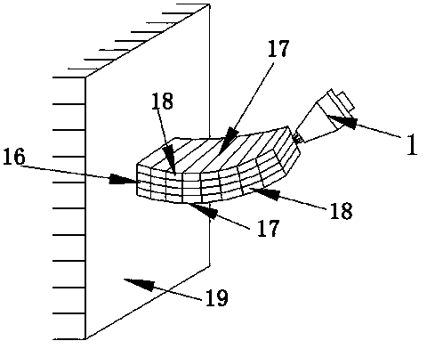
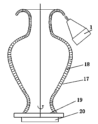
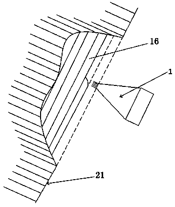
[0048] Embodiment three: see Figure 7 and 8 As shown in the figure, the simultaneous powder-feeding space laser processing and three-dimensional forming of curved and overhanging structural parts adopts the method of sub-area, and divides the forming unit into several layers along the optimal growth and accumulation direction, and each layer is divided into a boundary area 18 and a filling area 16 . The layering principle of the boundary area 18 is: slice and layer along the boundary surface 17 which is always perpendicular to the boundary surface normal direction. When the boundary surface is straight, the layers are parallel to each other. When the boundary surface is a curved surface, each layer is mutually parallel. It may be non-parallel and unequal thickness; the layering principle of the filling area 16 is: the layers are all parallel to the base surface 19, and the layers are also parallel to each other. After the cladding forming of a layer is completed, the nozzle...


PUM


Abstract

The invention discloses a synchronous powder feeding space laser machining and three-dimensional forming method and device. A three-dimensional solid is divided into a plurality of forming units according to the form simplification and nozzle fusion covering scanning accessibility principle, each forming unit is divided into a plurality of laminates, a mode for single-beam gas-carried powder feeding in a hollow annular laser is adopted, a mechanical arm is controlled to drive an in-laser powder feeding nozzle to move for scanning in filling areas and boundary areas of the laminates according to a preset trajectory, and forming fusion covering and stacking forming of the laminates are sequentially completed, so that forming fusion covering and stacking forming of the whole unit are completed. The device comprises the in-laser powder feeding nozzle, a laser generator, the mechanical arm, a control module, a transmission optical fiber, a gas-carried powder feeder and a gas source. The control module is connected with the mechanical arm, the laser generator and the gas-carried powder feeder. The in-laser powder feeding nozzle is fixed to the front end of the mechanical arm and can make spatial motion along with the mechanical arm. Through the method and device, fusion covering and three-dimensional stacking forming on any surface of the space can be achieved, and supportless three-dimensional forming of parts with complex structures such as a hanging structure and a cavity can be achieved.

Description

technical field [0001] The invention relates to a laser processing and forming technology, in particular to a method and device for synchronous powder feeding space laser processing and three-dimensional forming. Background technique [0002] Additive manufacturing technology is a technology that uses the method of gradually accumulating materials to manufacture solid parts. Among them, there are two methods of laser additive manufacturing commonly used for metals: laser powder bed selective sintering and melting and laser synchronous feeding cladding forming. Selective sintering is supported by a powder bed, and can form metal parts with complex shapes and overhanging structures, but the equipment is expensive, the cost is high, and the forming size is limited. The laser synchronous feeding method cladding and forming metal can approach or reach the performance of forgings, and the cost is low. This process can be integrated with various CNC processing machine tools and mo...

Claims


Application Information

Patent Timeline
Patent Type & Authority Applications(China)
IPC IPC(8): B22F3/105B23K26/144
CPCB23K26/144B22F5/10B22F7/062Y02P10/25B22F10/30B22F12/53B22F10/385B22F10/25B22F10/322B23K26/342B23K26/0884B22F3/105B33Y10/00B33Y30/00B22F2998/10B23K26/1476
Inventor 石世宏石拓傅戈雁朱刚贤史建军雷定中孟伟栋
Owner SUZHOU UNIV
Why Eureka
Try Eureka