Horizontal pushing and clamping type two-cylinder double-side braking retarder actuator

An actuating device and dual-cylinder technology, which is applied in rail brakes, transportation and packaging, railway car body components, etc., can solve the problem of not being able to realize single-track control cars and double-track control cars at the same time, complicated clamping manufacturing process, and unfavorable use of hydraulic systems, etc. problem, to achieve the effect of low pressure, easy lubrication and reasonable structure

Active Publication Date: 2014-12-10
西安优势铁路新技术有限责任公司
View PDF7 Cites 3 Cited by
  • Summary
  • Abstract
  • Description
  • Claims
  • Application Information

AI Technical Summary

Problems solved by technology

[0003] The mechanical structure of the actuator of the swing clamp type double-sided brake reducer is relatively complicated, the manufacturing process of the clamp is complicated and the cost is high, and the sleeve of the clamp is easy to wear during work
The actuator parts of the swing clamp type double-sided brake reducer actuator are located under the basic rail, which makes installation and maintenance inconvenient
[0004] The actuators of flat-push inner support type reducers are generally single-sided brakes. Under the same braking force requirements, compared with other reducer actuators, they need to provide higher system pressure, which is not conducive to oil cylinders, hydraulic pipelines, seals, etc. The use of hydraulic system actuators
[0005] The existing gravity reducer actuators of Hump Automation are divided into single-track control vehicles and double-track control vehicles, which cannot realize single-track control vehicles and dual-track vehicle control at the same time. The non-gravity reducer actuators can provide a maximum of 4 control stages. class

Method used


Image

  • Horizontal pushing and clamping type two-cylinder double-side braking retarder actuator
  • Horizontal pushing and clamping type two-cylinder double-side braking retarder actuator
  • Horizontal pushing and clamping type two-cylinder double-side braking retarder actuator

Examples


Embodiment Construction

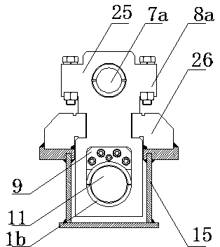
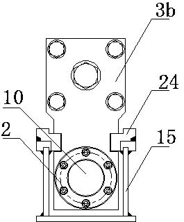
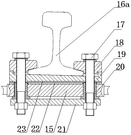
[0030] This embodiment provides a figure 1 The shown double-cylinder flat-push pincer type double-sided brake reducer actuator includes a joist 15, a left basic rail 16a and a right basic rail 16b that are arranged on the top surfaces of the left and right ends of the joist 15 and are parallel to each other, The double-acting oil cylinder that is arranged between the left basic rail 16a and the right basic rail 16b and is connected to the top surface of the joist 15 through the cylinder support slider 28 is arranged on the outside of the left basic rail 16a and the right basic rail 16b and passes through the outer support seat The left outer support seat 4a and the right outer support seat 4b that the slider 29 is connected with the top surface of the joist 15 are arranged on the outside of the left basic rail 16a and the right basic rail 16b and pass through the top of the inner support seat slider and the joist 15. The left inner support seat 6a and the right inner support s...


PUM


Abstract

The invention relates to a horizontal pushing and clamping type two-cylinder double-side braking retarder actuator comprising a bearer beam, inner supports, outer supports, brake rails and cylinders. The inner supports and the outer supports are arranged on two sides of two base rails, respectively. One brake rail is disposed on the inner supports. The other brake rail is arranged on the outer supports. The cylinders arranged over the bearer beam are connected with the inner supports. A brake unit is provided for any base rail. The actuator can be used with an electro-hydraulic control system to allow single-rail vehicle control and double-rail vehicle control, six-stage control can be achieved, many-stage vehicle control is available, and vehicle control precision is improved. The use of rectangular guide rails ensures large contact area of a kinematic pair and small pressure; lubricating is easy; wear loss is low; the service life is long; a processing technique is simple.

Description

technical field [0001] The invention relates to a dual-cylinder flat-push clamp type double-sided brake reducer actuator. Background technique [0002] At present, the reducer actuators used in hump automation in my country are divided into gravity reducer actuators and non-gravity reducer actuators. The main structures are swing clamp type and flat push inner support type. [0003] The mechanical structure of the actuator of the swing-clamp type double-sided brake reducer is relatively complicated, the manufacturing process of the clamp is complicated, the cost is high, and the sleeve of the clamp is easy to wear during work. The actuator parts of the swing clamp type double-sided brake reducer actuator are located under the basic rail, which causes inconvenience to installation and maintenance. [0004] The actuators of flat-push inner support type reducers are generally single-sided brakes. Under the same braking force requirements, compared with other reducer actuators,...

Claims


Application Information

Patent Timeline
Patent Type & Authority Applications(China)
IPC IPC(8): B61K7/08
Inventor 晁中叶陈森盛吕赛锐
Owner 西安优势铁路新技术有限责任公司
Why Eureka
Try Eureka