Drying box for drying electronic transformer body

An electronic transformer, drying box technology, applied in drying, furnace type, drying of solid materials, etc., to achieve the effect of simple structure, improved drying effect, and uniform drying

Active Publication Date: 2014-12-10
ANHUI HEHAN OPTOELECTRONICS TECH
View PDF6 Cites 13 Cited by
  • Summary
  • Abstract
  • Description
  • Claims
  • Application Information

AI Technical Summary

Problems solved by technology

[0003] The purpose of the present invention is to solve the above-mentioned technical problems existi

Method used


Image

  • Drying box for drying electronic transformer body
  • Drying box for drying electronic transformer body

Examples


Embodiment 1

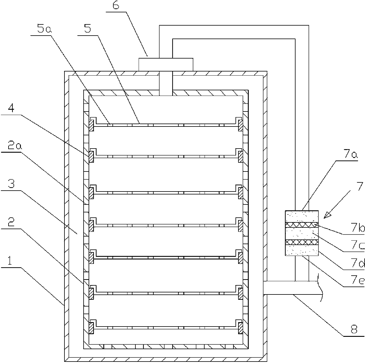
[0016] Such as figure 1 As shown, a drying box for drying the body of an electronic transformer provided by the present invention includes a box shell 1 and a box inner wall 2, and an air duct 3 communicating with an air intake pipe 8 is provided between the shell and the inner wall , a heating device is arranged in the air duct, and a group of ventilation holes 2a communicating with the air duct 3 are evenly distributed on the inner wall 2 of the box, and a set of supporting plates 4 are respectively provided on the corresponding sides of the inner wall, and there are sliding holes between the corresponding supporting plates 4 Cooperating storage trays 5, each storage tray 5 bottom is provided with a group of through holes 5a, the outer side of the box shell 1 is provided with an exhaust device 6, one end of the exhaust device communicates with the inner wall 2 of the cabinet through a pipeline, and the other end is connected with a drying device. Filtration device 7, describ...

Embodiment 2

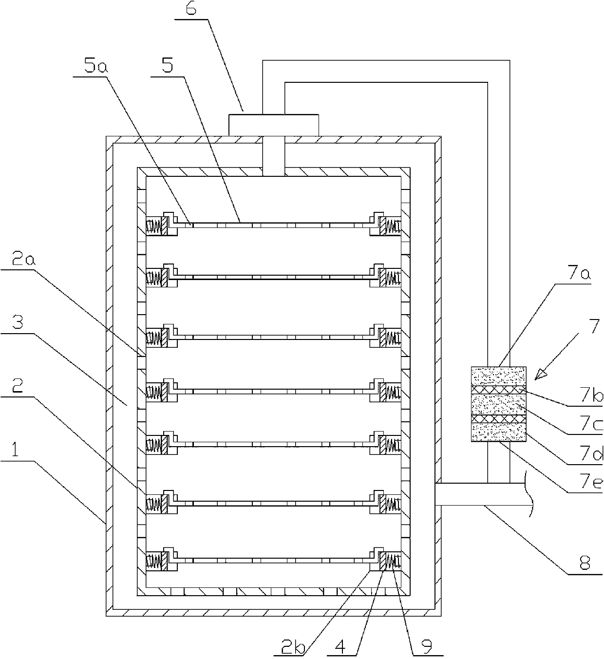
[0018] Such as figure 2 As shown, a drying box for drying the body of an electronic transformer provided by the present invention includes a box shell 1 and a box inner wall 2, and an air duct 3 communicating with an air intake pipe 8 is provided between the shell and the inner wall , a heating device is provided in the air duct, and a group of ventilation holes 2a communicating with the air duct 3 are evenly distributed on the inner wall 2 of the box. A set of supporting plates 4 are respectively arranged on the corresponding sides of the inner wall, and the corresponding box at both ends of each supporting plate 4 The internal wall 2 is provided with a chute 2b, and the supporting plate 4 is slidably matched with the chute 2b along the horizontal direction. The symmetrical position on one side of each supporting plate 4 is respectively provided with a spring 9, one end of the spring 9 is connected with the supporting plate 4, and the other One end is connected and matched w...


PUM


Abstract

The invention relates to a drying box for drying an electronic transformer body. The drying box comprises a box body outer shell (1) and a box body inner wall (2). An air channel (3) communicated with an air inlet pipe (8) is arranged between the outer wall and the inner wall. A heating device is arranged in the air channel. A group of ventilation holes (2a) communicated with the air channel are evenly formed in the inner wall of the box body inner wall. The drying box is characterized in that the two corresponding sides of the inner wall are respectively provided with a group of supporting plates (4), object placing trays (5) which are matched with the supporting plates in a sliding mode are connected between the corresponding supporting plates, an air extracting device (6) is arranged on the outer side of the box body outer shell, one end of the air extracting device (6) is communicated with the inner wall of the box body through a pipeline, the other end of the air extracting device is connected with a drying filtering device (7), and one end of the drying filtering device is communicated with the air inlet pipe. The drying box has the advantages that the problem that an existing drying box cannot process gas with moisture and gas with poisonous and harmful components is solved, the inner space using rate of the drying box is high, and drying efficiency is high.

Description

technical field [0001] The invention relates to a drying box, in particular to a drying box for drying the body of an electronic transformer. Background technique [0002] The body of the electronic transformer is mainly composed of a skeleton, iron core, coil and insulating materials. After the body is assembled, it must go through a drying process to control its water content within the limit of product quality requirements to ensure that the electronic transformer Have sufficient dielectric strength and operating life. At present, electronic transformers often use drying ovens for hot air drying. When drying, the insulating materials of electronic transformers will release gases containing moisture and toxic and harmful components. However, the existing drying ovens cannot process gases containing moisture and toxic and harmful components. , and the internal space utilization rate of the drying box is low, and the drying efficiency is low. Contents of the invention ...

Claims


Application Information

Patent Timeline
IPC IPC(8): F26B3/06
Inventor 夏云
Owner ANHUI HEHAN OPTOELECTRONICS TECH
Why Eureka
Try Eureka