Micro-gyroscope measurement system and method for measuring zero-bias stability by using system

A zero-bias stability, measurement system technology, applied in measurement devices, instruments, etc., to achieve the effect of simple structure

Inactive Publication Date: 2014-12-10
HARBIN INST OF TECH
View PDF13 Cites 8 Cited by
  • Summary
  • Abstract
  • Description
  • Claims
  • Application Information

AI Technical Summary

Problems solved by technology

[0009] The purpose of the present invention is to solve the problem that the lack of a large amount of data testing and comparison system for the performance of micro-gyroscope chips in the prior art leads to the problem that the selection of micro-gyroscopes can only be based on the performance indicators in the data booklet, and provides a micro-gyroscope measurement System and method for measuring bias stability using the system

Method used


Image

  • Micro-gyroscope measurement system and method for measuring zero-bias stability by using system
  • Micro-gyroscope measurement system and method for measuring zero-bias stability by using system
  • Micro-gyroscope measurement system and method for measuring zero-bias stability by using system

Examples


specific Embodiment approach 1

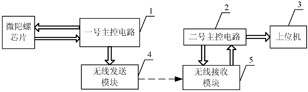
[0041] Specific implementation mode one: combine figure 1 Describe this embodiment, the micro-gyroscope measurement system described in this embodiment includes No. 1 main control circuit 1, No. 2 main control circuit 2, upper computer 3, wireless sending module 4 and wireless receiving module 5;

[0042] The No. 1 main control circuit 1 is used to configure the micro-gyroscope, update the on-chip FLASH of the micro-gyroscope, store configuration information, and read angular velocity data from the micro-gyroscope, and pass the read data through the wireless sending module 4 and the wireless receiving module 4. Module 5 sends to No. 2 main control circuit 2;

[0043] The second main control circuit 2 is used to send the received data to the upper computer 3;

[0044] The upper computer 3 is used to verify whether the configuration information has been written into the micro-gyroscope, and to calculate the received angular velocity data to obtain the zero-bias stability of the...

specific Embodiment approach 2

[0051] Specific Embodiment 2: This embodiment is a further limitation of the micro-gyroscope measurement system described in Embodiment 1. In this embodiment, the No. 1 main control circuit 1 and the No. 2 main control circuit 2 are both processed by STM32F103C8 implement.

[0052] The core of the STM32F103C8 processor is a high-performance ARM Cortex-M332-bit RISC, the operating frequency is 72MHz, and the data processing speed is fast; and the processor has rich enhanced I / O ports and peripherals connected to two APB buses , to facilitate system design. The device contains 2 12-bit ADCs, 3 general-purpose 16-bit timers and a PWM timer, and also includes standard and advanced communication interfaces: up to 2 I2C and SPI, 3 USARTs, a USB and a CAN, convenient Expansion of communication and system functions. The No. 1 main control circuit 1 of the system communicates with wireless and micro-gyroscope through two SPI interfaces respectively, communicates with host computer 3 ...

specific Embodiment approach 3

[0053] Specific Embodiment Three: This embodiment is a further limitation of the micro-gyroscope measurement system described in Embodiment 1. In this embodiment, the configuration information includes micro-gyroscope range selection, micro-gyroscope correction word, and micro-gyroscope sampling frequency and Bartlett window FIR digital filter options.


PUM


Abstract

The invention discloses a micro-gyroscope measurement system and a method for measuring zero-bias stability by using the system, relates to the performance testing technology of a micro-gyroscope chip and aims at solving the problem that the micro-gyroscope is only selected based on the performance indexes of a data manual due to the lack of a system for testing and comparing mass data on account of the performance of the micro-gyroscope chip in the prior art. The method takes an STM32F103C8 chip as a core processor for communicating with the micro-gyroscope, and comprises the following steps: firstly configuring the micro-gyroscope, then sending information such as angle speed measured by the micro-gyroscope to an upper computer by virtue of a wireless manner, processing the data by virtue of the upper computer and calculating by virtue of Allan variance to obtain the zero-bias stability of the micro-gyroscope. The micro-gyroscope measurement system is simple in structure, is capable of acquiring a large amount of data measured by the micro-gyroscope, processing the data by virtue of software to obtain the zero-bias stability of the micro-gyroscope and providing reliable basis for the selection of the micro-gyroscope, and is suitable for application of a micromachined gyroscope.

Description

technical field [0001] The invention relates to the performance testing technology of a micro-gyroscope chip. Background technique [0002] Micro gyro, also known as angular velocity meter, is an inertial sensor used to measure the angular velocity of an object rotating relative to inertial space. It has extremely important applications in aerospace, military, civil and many other fields, and is a key technology for the development of various countries. According to the production principle and structure, micro-gyroscopes can be roughly divided into three categories: mechanical micro-gyroscopes, optical micro-gyroscopes, and micro-mechanical micro-gyroscopes. The mechanical gyroscope is a rotating gyroscope manufactured by machining, which uses the principle of conservation of angular momentum of a high-speed rotating object to measure the angular velocity. This gyroscope has high precision, but its structure is complicated, its cost is high, and its service life is limite...

Claims


Application Information

Patent Timeline
IPC IPC(8): G01C25/00
CPCG01C25/00
Inventor 马广富杜少鹤郭延宁张超孙延超董宏洋李传江
Owner HARBIN INST OF TECH
Why Eureka
Try Eureka