
Oil immersed transformer

An oil-immersed transformer and oil tank technology, applied in the field of transformers, can solve the problems of increasing material consumption, narrow application temperature range, and increasing central wire consumables, etc., to increase oil circulation strength and speed, wide application temperature range, and improve shock absorption performance effect

Inactive Publication Date: 2014-12-10
HUANGYANG ELECTRIC POWER +2
View PDF5 Cites 6 Cited by
  • Summary
  • Abstract
  • Description
  • Claims
  • Application Information

AI Technical Summary

Problems solved by technology

[0002] The oil-immersed transformer will continue to increase the oil temperature during the working process. The oil temperature generally passes through the circulation between the tank wall and the inside of the tank to reduce the oil temperature. However, the oil circulation process between the inner wall and the inside of the tank is slow, and the convection strength of the oil is low. , which is not conducive to reducing the oil temperature of the oil-immersed transformer, and it is easy to cause the oil temperature inside the oil-immersed transformer to rise continuously under high-intensity work, which has potential safety hazards; the transformer will generate noise pollution due to its own vibration during the working process, which will affect the surrounding environment. People's work and rest; the traditional high-voltage coil wire has low withstand voltage strength, narrow application temperature range, low tensile strength of the insulating layer, which is not conducive to wrapping, and the thickness of the insulating layer is large. When winding the coil, the central wire consumables are increased and the production is increased Cost; the length of the exposed part of the compression nut and the conductive rod of the traditional low-voltage terminal is large, the length of the conductive rod is long, and the fastening bolt is arranged on the side of the conductive rod, which increases the amount of materials and high cost. Immersed Transformer for Improvement

Method used


Image

  • Oil immersed transformer
  • Oil immersed transformer
  • Oil immersed transformer

Examples


Embodiment Construction

[0016] The following will clearly and completely describe the technical solutions in the embodiments of the present invention with reference to the accompanying drawings in the embodiments of the present invention. Obviously, the described embodiments are only some, not all, embodiments of the present invention. Based on the embodiments of the present invention, all other embodiments obtained by persons of ordinary skill in the art without making creative efforts belong to the protection scope of the present invention.

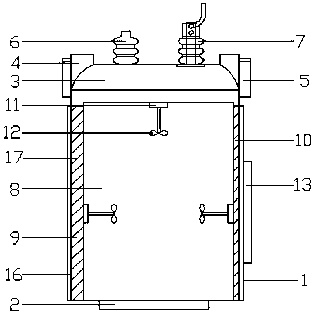
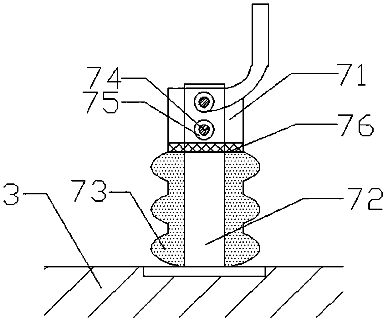
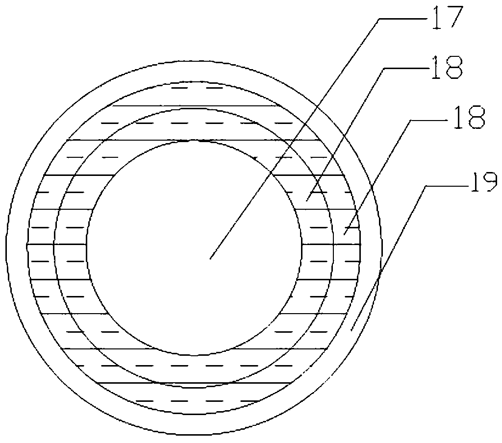
[0017] see Figure 1~5 , in an embodiment of the present invention, an oil-immersed transformer includes a box body 1 and a shock-absorbing base 2, a box cover 3 is provided on the upper part of the box body 1, and a guard plate 4 is provided on the edge of the box cover 3, and the guard plate 4 and the The lock clip 5 is connected; the cover 3 is provided with a high-voltage terminal 6 and a low-voltage terminal 7, and the low-voltage terminal 7 includes a te...


PUM


Abstract

The invention discloses an oil immersed transformer comprising a tank and a damping base. A tank cover is arranged on the upper portion of the tank, a high tension terminal and a low tension terminal are arranged on the tank cover, the low tension terminal comprises a connector lug, a conducting rod and a porcelain bushing, the lower portion of the conducting rod is sleeved with the porcelain bushing, and the upper portion of the conducting rod is sleeved with the connector lug. An oil tank is arranged in the tank, a high tension coil and a low tension coil are arranged in the oil tank, and a stirring device is mounted on each side of the inner wall of the oil tank through a fixing piece. An oil-level display is arranged on the outer wall of the tank. The damping base is arranged at the bottom of the tank and comprises three damping strips forming a triangle by encircling, each damping strip is U-shaped, and damping springs are arranged between an upper face plate and a lower face plate of each damping strip. The oil immersed transformer is simple in structure, reliable in mounting, firm in connection, raw material saving and high in dielectric breakdown strength; vibration generated when the transformer is operated can be reduced effectively, so that noise is reduced; circulating speed of oil in the oil tank can be increased effectively, and heat dissipation performance of equipment is improved.

Description

technical field [0001] The invention relates to a transformer, in particular to an oil-immersed transformer. Background technique [0002] The oil-immersed transformer will continue to increase the oil temperature during the working process. The oil temperature generally passes through the circulation between the tank wall and the inside of the tank to reduce the oil temperature. However, the oil circulation process between the inner wall and the inside of the tank is slow, and the convection strength of the oil is low. , which is not conducive to reducing the oil temperature of the oil-immersed transformer, and it is easy to cause the oil temperature inside the oil-immersed transformer to rise continuously under high-intensity work, which has potential safety hazards; the transformer will generate noise pollution due to its own vibration during the working process, which will affect the surrounding environment. People's work and rest; the traditional high-voltage coil wire ...

Claims


Application Information

Patent Timeline
IPC IPC(8): H01F27/14H01F27/29H01F27/30H01F27/36H01F27/32
CPCF16F15/04H01F27/04H01F27/06H01F27/14H01F27/292H01F27/324
Inventor 蒋根大吴雨森
Owner HUANGYANG ELECTRIC POWER
Learn More