
Rotor Levitation Control Method of Stator Permanent Magnet Bearingless Synchronous Motor

A synchronous motor, suspension control technology, applied in the field of electric motors, can solve the problems of short life, increasing the complexity and cost of motor manufacturing, permanent demagnetization of permanent magnets, etc.

Active Publication Date: 2017-01-18
SOUTHEAST UNIV
View PDF5 Cites 0 Cited by
  • Summary
  • Abstract
  • Description
  • Claims
  • Application Information

AI Technical Summary

Problems solved by technology

The working principle of this kind of rotor permanent magnet synchronous motor is intuitive, but there are three outstanding disadvantages: 1) the rotor permanent magnet is difficult to dissipate heat, and there is a risk of permanent demagnetization of the permanent magnet due to temperature rise; The centrifugal force of the rotor must take special reinforcement measures; 3) In order to obtain the sinusoidal back EMF waveform, it is usually necessary to adopt a special design of the shape of the permanent magnet, which increases the complexity and cost of motor manufacturing
At present, the stator permanent magnet flux switching synchronous motor rotors are all supported by mechanical bearings. This mechanical bearing support restricts the increase of the rotor speed. At the same time, the wear of the mechanical bearings brings pollution, short life and other problems.

Method used

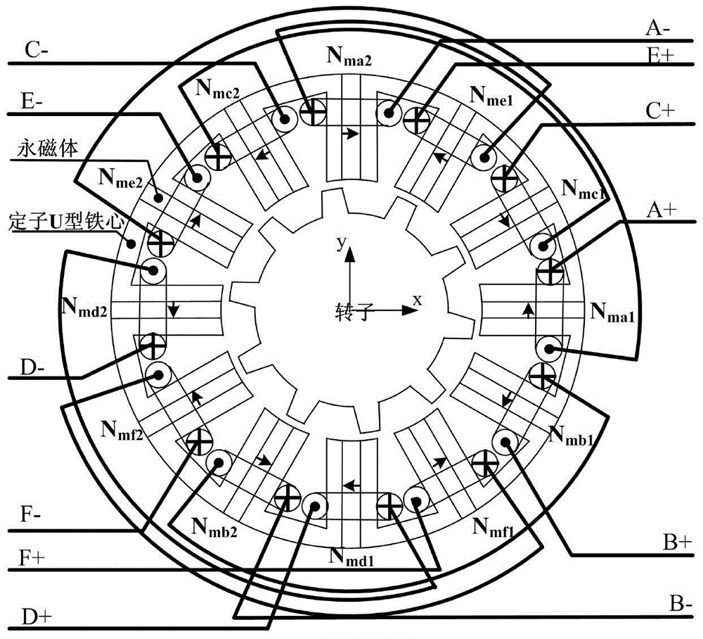
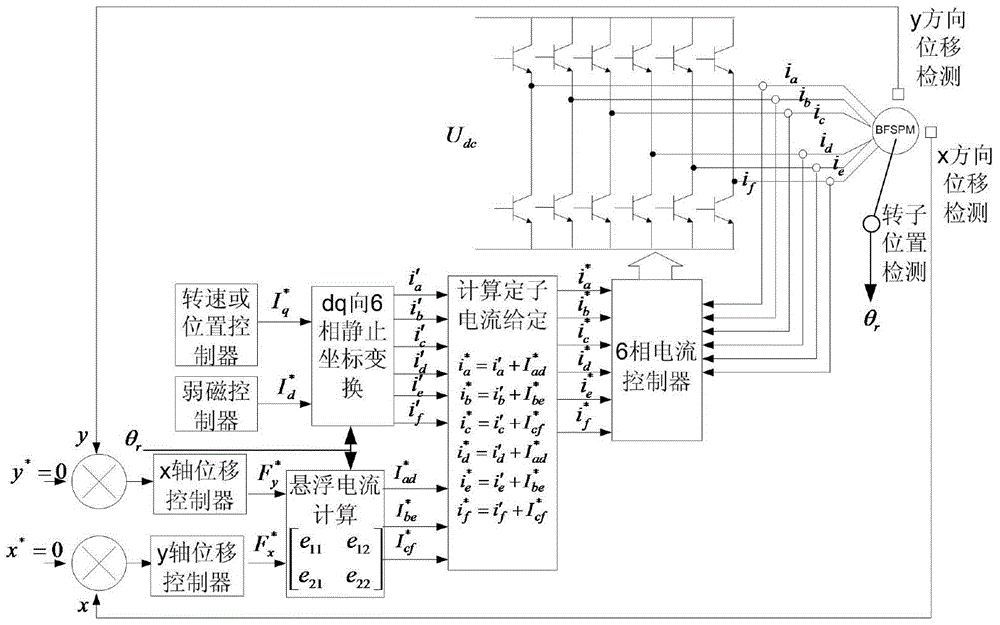
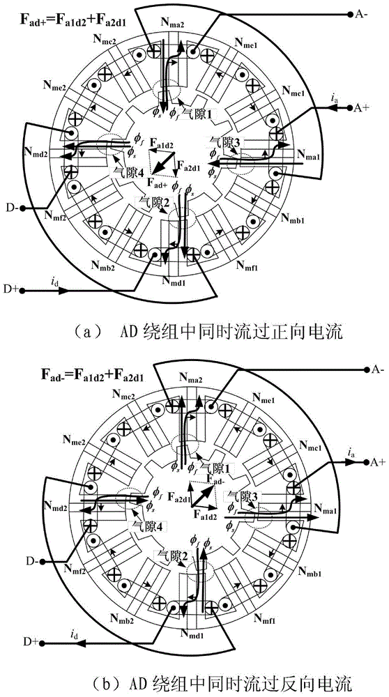

Image

  • Rotor Levitation Control Method of Stator Permanent Magnet Bearingless Synchronous Motor
  • Rotor Levitation Control Method of Stator Permanent Magnet Bearingless Synchronous Motor
  • Rotor Levitation Control Method of Stator Permanent Magnet Bearingless Synchronous Motor

Examples


Embodiment Construction

[0043] Certain terms are used, for example, in the description and claims to refer to particular components. Those skilled in the art should understand that hardware manufacturers may use different terms to refer to the same component. The specification and claims do not use the difference in name as a way to distinguish components, but use the difference in function of components as a criterion for distinguishing. As mentioned throughout the specification and claims, "comprising" is an open term, so it should be interpreted as "including but not limited to". "Approximately" means that within an acceptable error range, those skilled in the art can solve the technical problem within a certain error range and basically achieve the technical effect. In addition, the term "coupled" herein includes any direct and indirect electrical coupling means. Therefore, if it is described that a first device is coupled to a second device, it means that the first device may be directly elect...


PUM


Abstract

The invention relates to a rotor suspension control method for a stator permanent magnet type bearingless synchronous motor. In the winding of a six-phase single winding stator permanent magnet type synchronous motor, a current symmetrical component for controlling torque and a suspension component for controlling the rotor suspending power flow through simultaneously; on the basis of the finite element analysis or an experimental measuring method, the relations of all coefficients in a rotor suspending power model and rotor position angles are determined; the active component, the reactive component, the rotor position angles, and radial suspending power component given values output by x-axis and y-axis rotor radial displacement controllers in the current symmetrical component flowing through the winding are sent to the provided rotor suspending power mathematical model, and the suspension component for controlling the rotor suspending power in the winding current is output. According to the method provided by the invention, through the adoption of the current closed-loop control method, the closed-loop control of the current symmetrical component and the suspension component for controlling the rotor suspending power can be realized simultaneously, and finally, the rotation of the six-phase single winding stator permanent magnet type synchronous motor under the rotor suspension state can be realized.

Description

technical field [0001] The invention relates to the field of motors, in particular to a rotor suspension control method of a stator permanent magnet type bearingless synchronous motor. Background technique [0002] Permanent magnet synchronous motors use permanent magnets to provide excitation, and have the advantages of high efficiency and small size, and are widely used in industry. The vast majority of permanent magnet synchronous motors currently in use adopt a rotor permanent magnet structure, that is, the permanent magnet is surface-mounted or inserted into the rotor core, and the stator winding flows through the current to generate a synchronous magnetic field to drive the rotor permanent magnet magnetic field to rotate synchronously. The working principle of this kind of rotor permanent magnet synchronous motor is intuitive, but there are three outstanding disadvantages: 1) the rotor permanent magnet is difficult to dissipate heat, and there is a risk of permanent de...

Claims


Application Information

Patent Timeline
Patent Type & Authority Patents(China)
IPC IPC(8): H02P21/12H02P21/22
Inventor 周扬忠程明
Owner SOUTHEAST UNIV
Learn More