Method for forming fluoride spray coating, and member coated with fluoride spray coating
A technology for covering parts and fluoride, which is applied in the direction of coating, fusion spraying, metal material coating process, etc., can solve problems such as quality reduction, and achieve the effect of excellent corrosion resistance
- Summary
- Abstract
- Description
- Claims
- Application Information
AI Technical Summary
Problems solved by technology
Method used
Image

Examples
Embodiment 1
[0113] In this example, the influence of the pretreatment of the substrate surface on the adhesion of the fluoride spray coating was investigated.
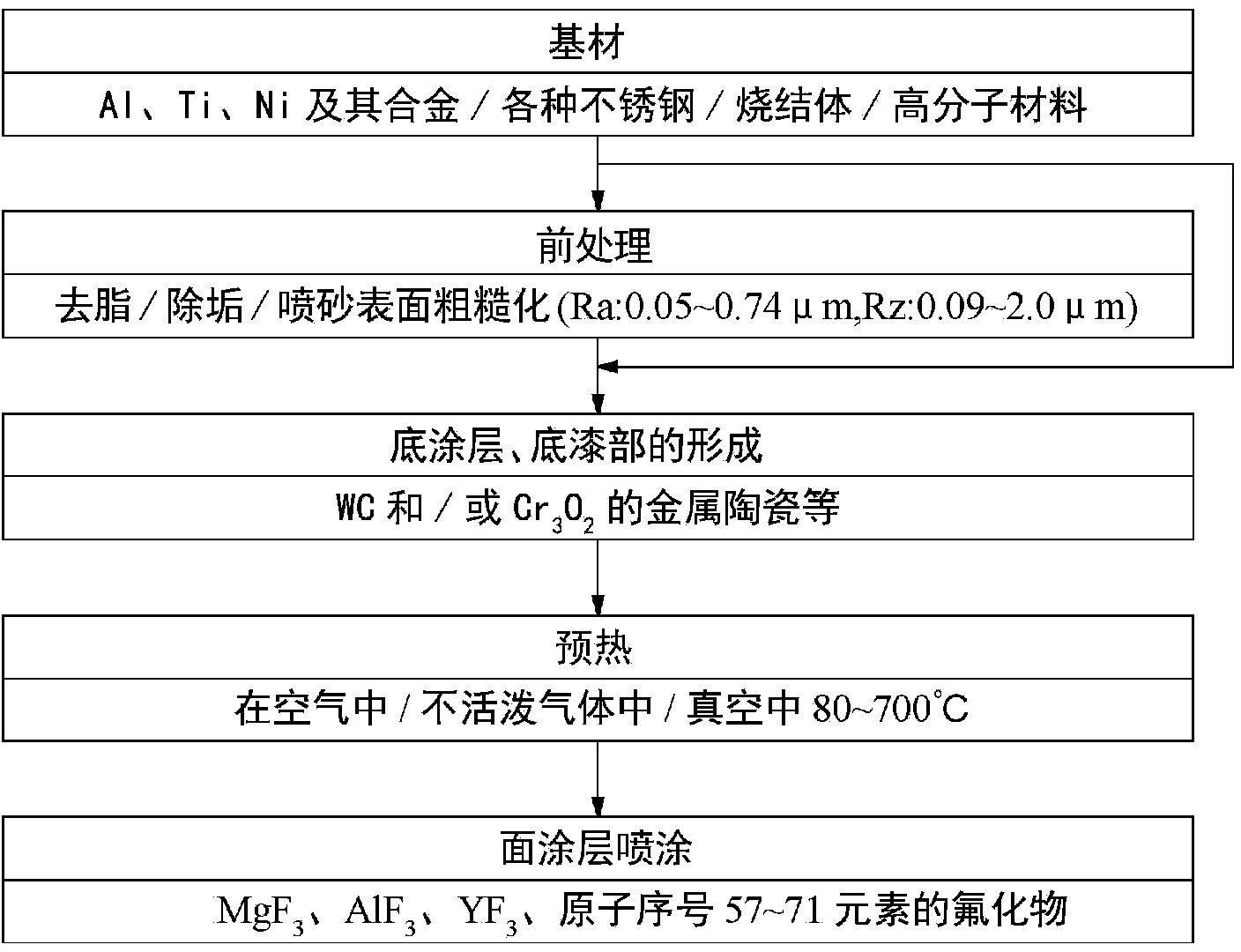
[0114] (1) Types of pretreatment
[0115] The following pretreatment was performed on one side of Al3003 alloy ("JIS M4000", size: diameter 25 mm×thickness 5 mm) as a base material.
[0116] (i) After degreasing, lightly grind with a wire brush.
[0117] (ii) After degreasing, Ni-20 mass % Cr was formed into a metal undercoat layer with a thickness of 50 μm by an atmospheric plasma spraying method (flying speed: 250 m / s).
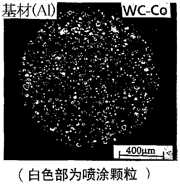
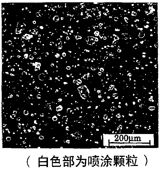
[0118] (iii) After degreasing, WC-12 mass % Co was sprayed sparsely (area ratio: 22%) using a high-speed flame spraying method (flight speed 580 m / s, number of spraying: 3 times) to form a primer part.
[0119] (iv) After degreasing, the Cr 3 C 2 -18 mass % Ni-7 mass % Cr An undercoat layer of carbide cermet with a thickness of 30 μm was formed by a high-speed flame spraying method (flight speed 560 m / s, nu...
Embodiment 2
[0138] In this example, the formation of YF with a thickness of 100 μm using SS400 steel as a base material and a reduced pressure plasma spraying method was investigated. 3 Adhesion of the spray coating when the coating is sprayed.
[0139] (1) Type of pretreatment (surface roughening, formation of intermediate layer)
[0140] The same kind of pretreatment method as in Example 1 was carried out.
[0141] (2) Formation of fluoride spray coating
[0142] YF with a thickness of 100 μm is formed by plasma spraying (decompression plasma spraying) in a reduced pressure environment of Ar gas of 100 to 200 hPa 3 .
[0143] (3) Adhesion test method of film
[0144] The same method as in Example 1 was carried out.
[0145] (4) Test results
[0146] The test results are shown in Table 2. From this result, it can be seen that YF is formed directly on the surface of the base material 3In the case of spray coating (No. 1), the adhesion force of the film formed after sandblasting wa...
Embodiment 3
[0154] In this example, YF formed by high-speed plasma spraying using SS400 steel as a base material is investigated 3 Adhesion of spray coating.
[0155] (1) Type of pretreatment (surface roughening, formation of intermediate layer)
[0156] The same pretreatment method as in Example 1 was carried out.
[0157] (2) Formation of fluoride spray coating
[0158] YF with a thickness of 100 μm is formed by high-speed plasma spraying 3 .
[0159] (3) Adhesion test method of film
[0160] It was implemented by the same method as Example 1.
[0161] (4) Test results
[0162] The test results are shown in Table 3. From this result, like the results of Example 1 and Example 2, it was confirmed that the primer part or primer layer (No. 3, 4, 7, 8) of the carbide cermet according to the present invention was formed with the substrate. Regardless of the presence or absence of surface roughening by sandblasting, a fluoride sprayed coating that often has high adhesion can be formed....
PUM
| Property | Measurement | Unit |
|---|---|---|
| thickness | aaaaa | aaaaa |
| particle diameter | aaaaa | aaaaa |
| thickness | aaaaa | aaaaa |
Abstract
Description
Claims
Application Information
 - R&D
- Intellectual Property
- Life Sciences
- Materials
- Tech Scout
- Unparalleled Data Quality
- Higher Quality Content
- 60% Fewer Hallucinations
Browse by: Latest US Patents, China's latest patents, Technical Efficacy Thesaurus, Application Domain, Technology Topic, Popular Technical Reports.
© 2025 PatSnap. All rights reserved.Legal|Privacy policy|Modern Slavery Act Transparency Statement|Sitemap|About US| Contact US: help@patsnap.com