Internal combustion engine

A technology for internal combustion engines and compressors, which is applied to internal combustion piston engines, combustion engines, mechanical equipment, etc., and can solve problems such as backflow of mixed gas from cross-cylinders

Inactive Publication Date: 2014-12-10
TOYOTA JIDOSHA KK
View PDF6 Cites 5 Cited by
  • Summary
  • Abstract
  • Description
  • Claims
  • Application Information

AI Technical Summary

Problems solved by technology

However, simply forming a single bypass passage that connects the upstream and downstream portions of the intake passage to share the entire bypass passage creates a new problem.
That is, for example, if the valve provided in the bypass passage is opened in order to suppress chattering, a large amount of blow-by gas will suddenly flow back into the intake passage.

Method used


Image

  • Internal combustion engine
  • Internal combustion engine
  • Internal combustion engine

Examples


Embodiment Construction

[0047] Below, refer to Figure 1 ~ Figure 4 A first embodiment in which the internal combustion engine of the present invention is embodied will be described.

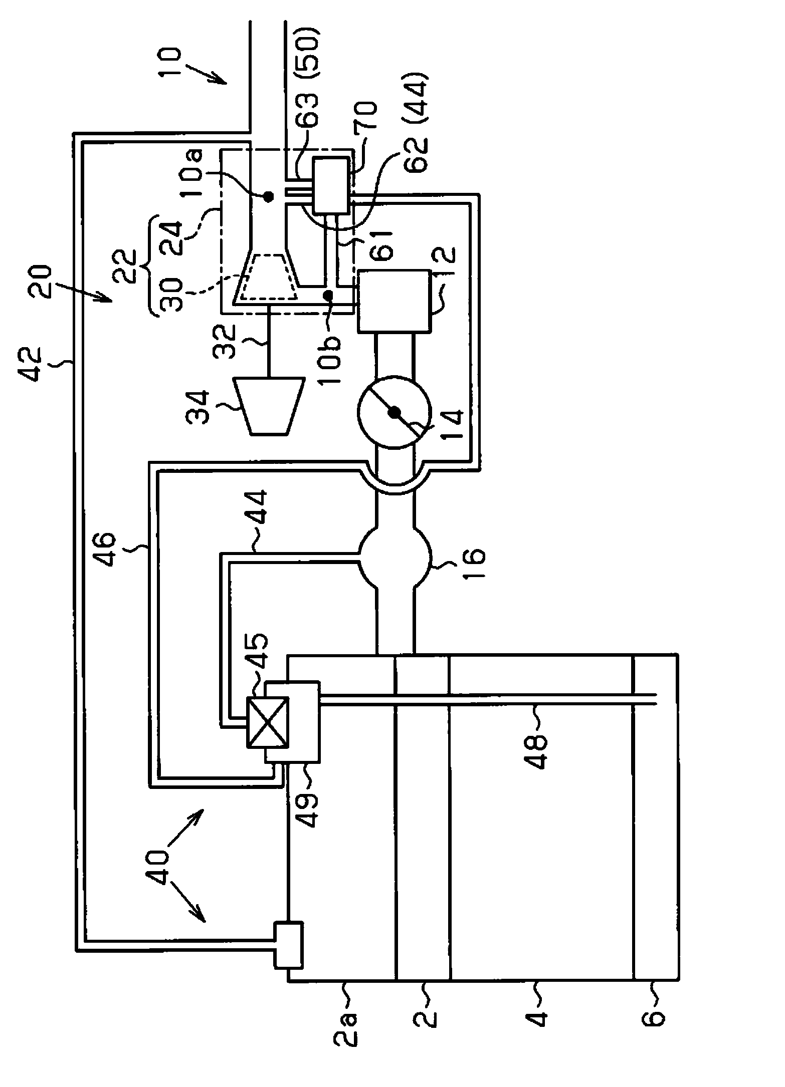
[0048] Such as figure 1 The internal combustion engine is shown with a cylinder head 2 , a cylinder block 4 and a crank housing 6 . In addition, a head cover 2 a is attached to an upper portion of the cylinder head 2 .

[0049] An intake passage 10 for introducing air to each cylinder is connected to the cylinder head 2 .

[0050] A compressor 22 , an intercooler 12 , a throttle valve 14 , and an intake manifold 16 are provided in this order from the upstream side in the intake passage 10 .

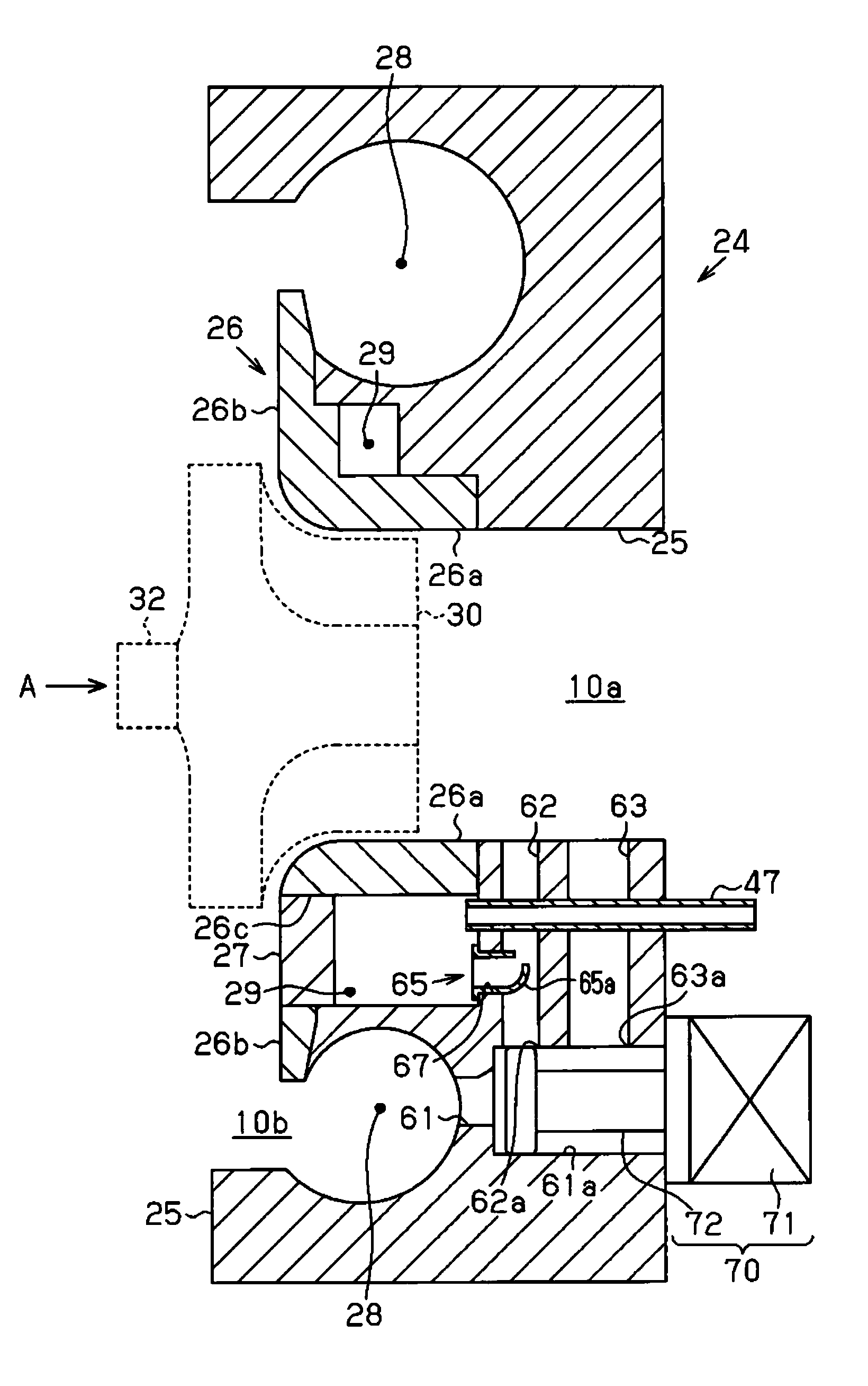
[0051] The compressor 22 has an impeller 30 provided in the intake passage 10 , and a compressor housing 24 surrounding the impeller 30 . In addition, in the intake passage 10 , a portion on the upstream side of the impeller 30 is referred to as an upstream portion 10 a , and a portion on the downstream side of the impeller 30...


PUM


Abstract

A second recirculation passage (46) recirculates blow-by gas at an upstream location (10a), which is upstream from an impeller (30) of an exhaust turbine supercharger (20) in an intake passage (10). A first passage (61) branches and extends from a downstream location (10b), which is downstream from the impeller (30) in the intake passage (10). A second passage (62) that forms a portion of the second recirculation passage (46) connects the first passage (61) and the upstream location (10a), and third passage (63) provided separately from the second passage (62) connects the first passage (61) and the upstream location (10a). A change mechanism (70) changes, under mutually different conditions, the flow volume of compressed gas recirculating to the upstream location (10a) through the second passage (62), and the flow volume of compressed gas recirculating to the upstream location (10a) through the third passage (63).

Description

technical field [0001] The invention relates to an internal combustion engine with an exhaust gas turbocharger and a blow-by gas return passage, wherein the exhaust gas turbocharger has a compressor with an impeller driven by the energy of the exhaust gas in the intake passage, and the blow-by gas return flow The passage causes the blow-by gas to flow back to the portion of the intake passage upstream of the impeller. Background technique [0002] Conventionally, an internal combustion engine having an exhaust turbocharger that drives an impeller of a compressor using the energy of exhaust gas is known (for example, refer to Patent Document 1). [0003] In addition, in the internal combustion engine, the blow-by gas in the crank case is returned to the intake passage via the blow-by gas return passage. In addition, in the case of a naturally aspirated internal combustion engine not equipped with an exhaust gas turbocharger, or a so-called "NA" internal combustion engine, th...

Claims


Application Information

Patent Timeline
IPC IPC(8): F01M13/00F02B37/00F02B39/00
CPCF05D2260/14F01M2013/027F01M13/022F05D2260/606F02B39/00F01D17/105F02B37/16F05D2220/40Y02T10/144F02M25/08F02M26/09Y02T10/12
Inventor 贞光贵裕中垣淳前田治矶谷知之饭田达雄米泽幸一
Owner TOYOTA JIDOSHA KK
Why Eureka
Try Eureka