Image processing device and method, and image processing program

一种图像处理装置、图像处理的技术,应用在图像数据处理、图像增强、图像分析等方向,能够解决分辨率降低等问题,达到高画质的效果

Inactive Publication Date: 2014-12-10
MITSUBISHI ELECTRIC CORP
View PDF4 Cites 0 Cited by
  • Summary
  • Abstract
  • Description
  • Claims
  • Application Information

AI Technical Summary

Problems solved by technology

[0009] In the method described in the above-mentioned Patent Document 1, continuous noise in a specific direction is sometimes misjudged as an edge, or a pattern existing in an object is misjudged as noise, which may cause a decrease in resolution and cannot perform sufficiently. noise reduction problem

Method used


Image

  • Image processing device and method, and image processing program
  • Image processing device and method, and image processing program
  • Image processing device and method, and image processing program

Examples


Embodiment approach 1

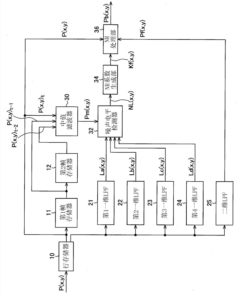
[0029] figure 1 The functional configuration of the image processing device according to Embodiment 1 of the present invention is shown.

[0030] The illustrated image processing device takes, as an input image, a moving image composed of a time series of multiple frames supplied from an image input system such as an image pickup device not shown or an image transmission system, for example. An image is composed of pixels arranged in a matrix in the horizontal direction (row direction) and vertical direction (vertical direction), and the input image data is composed of data representing pixel values ​​of pixels constituting the image arranged in raster order.

[0031] Next, it is assumed that the input image is an image input from a single-board color digital camera having pixels having Bayer-arranged color filters, and four pixels of R, Gr, Gb, and B are sequentially input from the imaging element in the order of arrangement of the pixels. The image signal of the captured co...

Embodiment approach 2

[0112] Figure 9 The functional configuration of the image processing device according to Embodiment 2 of the present invention is shown. exist Figure 9 in, right with figure 1 The same structural elements are labeled with the same reference numerals.

[0113] The same constituent elements as in Embodiment 1 are line memory 10, frame memories 11, 12, median filter 30, one-dimensional filters 21, 22, 23, 24, two-dimensional filter 25, noise level detection unit 32, and NR processing unit 36 ​​.

[0114] Embodiment 2 differs from Embodiment 1 in that a correction coefficient generation unit 38 is provided, and instead of figure 1An NR coefficient generation unit 44 is provided instead of the NR coefficient generation unit 34 .

[0115] The NR coefficient generation unit 44 has an NR coefficient calculation unit 44a and an NR coefficient correction unit 44b.

[0116] NR coefficient calculation unit 44a and figure 1 The NR coefficient generator 34 has the same configuratio...

Embodiment approach 3

[0132] Figure 11 The functional configuration of the image processing device according to Embodiment 3 of the present invention is shown. exist Figure 11 in, right with Figure 9 The same structural elements are labeled with the same reference numerals.

[0133] and implementation 2 ( Figure 9 ) are the line memory 10 , frame memories 11 , 12 , median filter 30 , one-dimensional filters 21 , 22 , 23 , 24 , and two-dimensional filter 25 .

[0134] The image processing device of Embodiment 3 replaces Figure 9 The noise level detection unit 32 , the NR processing unit 36 ​​and the NR coefficient generation unit 44 include a noise level detection unit 37 , an NR processing unit 39 and an NR coefficient generation unit 45 . The noise level detection unit 37, the NR processing unit 39, and the NR coefficient generation unit 45 are substantially the same as the noise level detection unit 32, the NR processing unit 36, and the NR coefficient generation unit 44, respectively, ...


PUM


Abstract

An NR coefficient (Kf) is calculated on the basis of a representative value of a target pixel and the low-pass filter value nearest to the representative value of the target pixel, said low-pass filter value being selected from among a plurality of different-direction one-dimensional low pass filter values corresponding to an input image, and the pixel value of the target pixel and a peripheral low-pass filter (25) are weighted by the NR coefficient (Kf) and added (36). The representative value of the target pixel might be, for example, a median value obtained by filtering a current frame and a past frame in the time axis direction. By this means, noise is reduced in the image processing device without lowering the resolution.

Description

technical field [0001] The present invention relates to an image processing device, method, and image processing program for removing noise mixed in an input image in a digital camera or the like. Background technique [0002] In an image input device such as a digital camera having an imaging element such as a CCD, and an image output device such as a monitor displaying an image input from such an image input device, noise is mixed into image data in an image input system or an image transmission system. This noise is typically removed by image processing within the device. A conventional method for removing noise mixed in such an image input device or image output device will be described. [0003] As the easiest general method of noise removal, there is a technique of constructing a processing window composed of a plurality of pixels centered on a pixel to be image processed (hereinafter referred to as a pixel of interest), and by processing the surrounding pixels within...

Claims


Application Information

Patent Timeline
Patent Type & Authority Applications(China)
IPC IPC(8): H04N5/232G06T5/00G06T5/20
CPCH04N5/357H04N5/23229H04N5/2173G06T5/20G06T2207/10016G06T2207/20182H04N25/60H04N23/80G06T5/70G06T2207/20024
Inventor 青木透桥本充夫的场成浩
Owner MITSUBISHI ELECTRIC CORP
Why Eureka
Try Eureka