Fixed type projection welder and multi-section projection welding method
A projection welding machine, fixed technology, applied in the direction of welding equipment, resistance welding equipment, electrode characteristics, etc., can solve the problems of difficult to guarantee the quality of solder joints, small size of solder joints, etc., to meet the requirements of welding and product size requirements , the effect of meeting the requirements of dimensional accuracy
Inactive Publication Date: 2014-12-17
上海宝井钢材加工配送有限公司
View PDF5 Cites 4 Cited by
- Summary
- Abstract
- Description
- Claims
- Application Information
AI Technical Summary
Problems solved by technology
[0004] The purpose of the present invention is to provide a fixed projection welding machine and a multi-stage projection welding method to solve the problems in the prior art that the size of the solder joints is too small and the quality of the solder joints is difficult to guarantee
Method used
View moreImage
Smart ImageViewing Examples

Examples
Embodiment 1
[0050] Device model
Embodiment 2
[0052] Device model
Login to View More PUM
| Property | Measurement | Unit |
|---|---|---|
| Depth | aaaaa | aaaaa |
| Bottom diameter | aaaaa | aaaaa |
Abstract
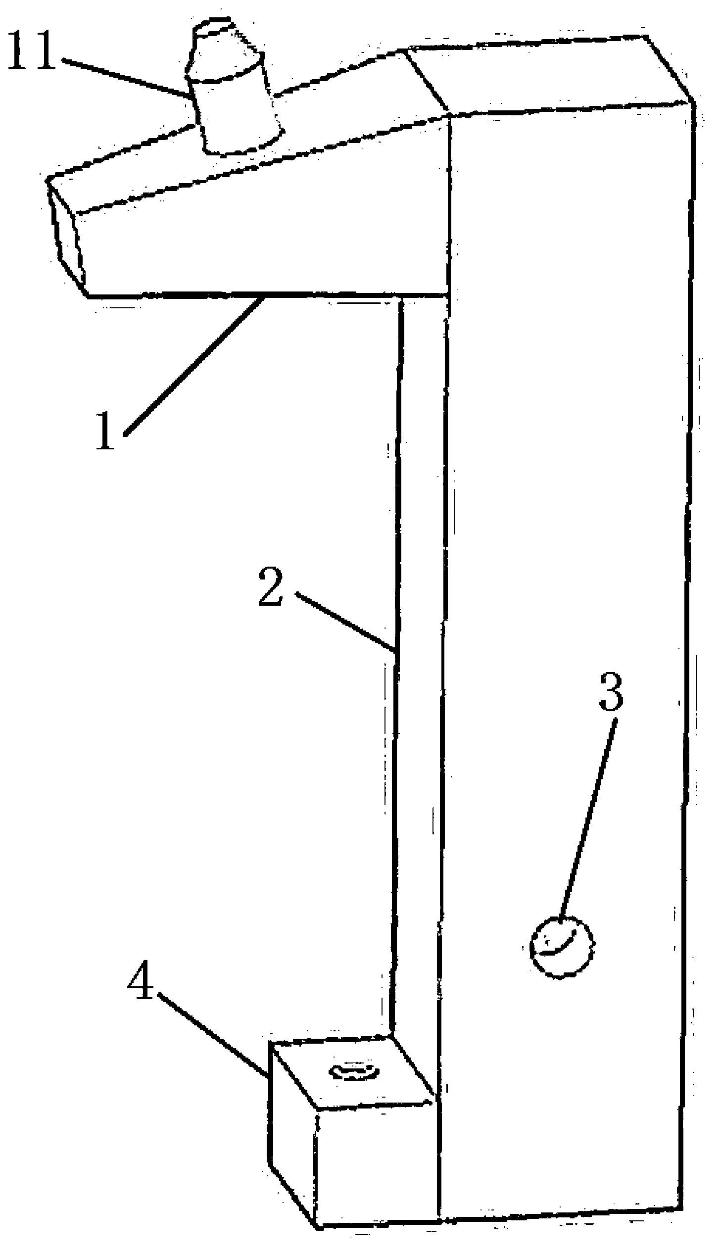
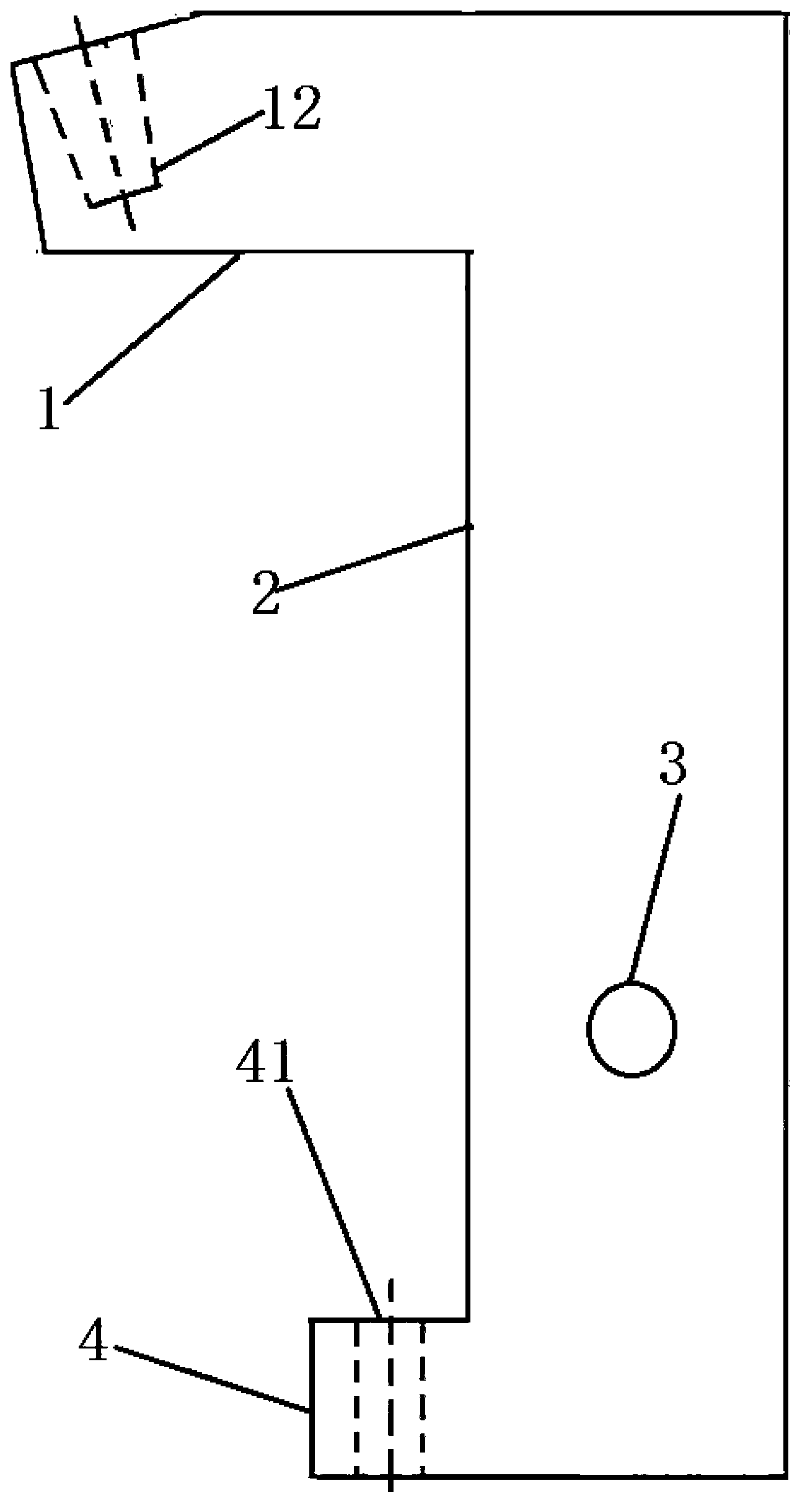
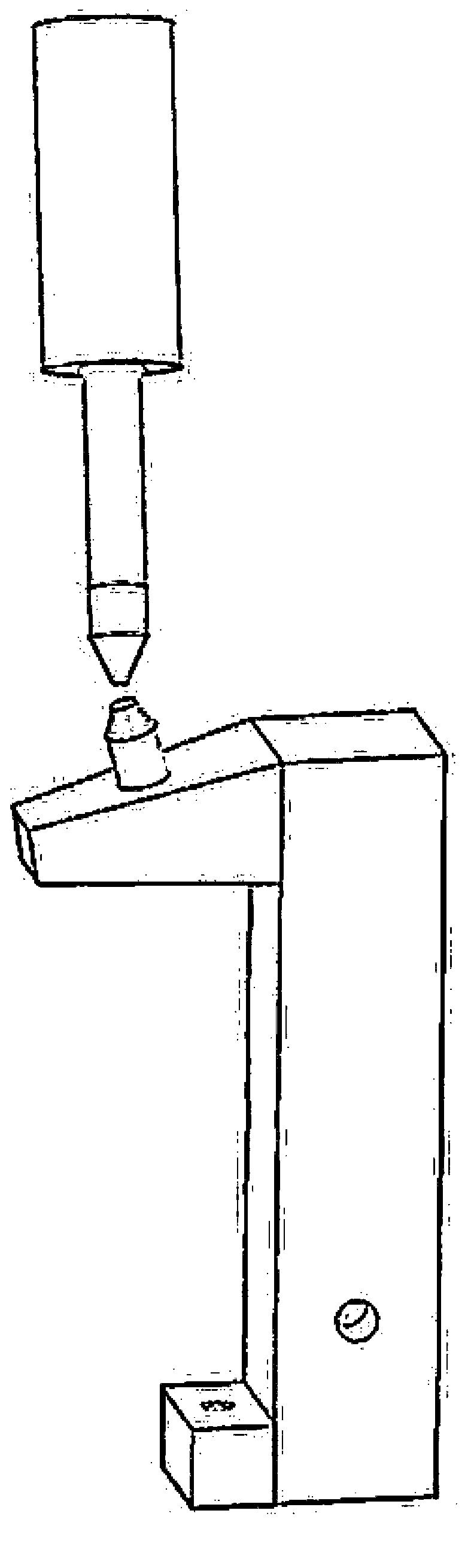
The invention discloses a fixed type projection welder. The fixed type projection welder comprises a lower electrode base. The lower electrode base comprises an electrode head base and an electrode base body. The electrode head base is arranged on the top of the electrode base body. An included angle is formed by the upper surface of the electrode head base and the horizontal direction. An electrode head is arranged on the electrode head base. The electrode base body comprises a cooling water inlet and a cooling water outlet, and the inlet and the outlet are respectively formed in the surface of the electrode base body. The electrode base body is internally provided with a cooling water channel connected with the electrode head, the cooling water inlet and the cooling water outlet. A multi-section projection welding method comprises the following steps that firstly, an inversion medium-frequency direct current welding device is utilized, secondly, a small assembly component is welded with two points through a cantilever type spot welding machine via a maturely designed welding clamp, and thirdly, the fixed type projection welder is utilized for welding the rest of welding spots in a strengthened mode. According to the fixed type projection welder and the multi-section projection welding method, the requirement for the performance for welding a high-strength steel plate can be met, a traditional spot welding technology is replaced, and the requirements for size precision, welding and product size are met.
Description
technical field [0001] The present invention relates to a component assembly resistance welding device and method, more specifically, to a fixed projection welding machine and a multi-stage projection welding method. Background technique [0002] At present, the common spot welding process is operated by cantilever spot welding machine equipment. The welding process is mature and can be completed through the cooperation of well-designed welding fixture tooling and welding tong angle. However, relying on such a welding method cannot meet the welding performance requirements and assembly size requirements of the high-strength assembly parts. [0003] In a welding cycle of the traditional bump welding process, the welding current is mainly concentrated in the middle section, and there is no need for preheating and postheating two parts of current for supplementary welding. Ordinary upper and lower electrode seats are cylindrical chrome-zirconium copper rods, and the upper and ...
Claims
Login to View More Application Information
Patent Timeline
 IPC IPC(8): B23K11/14B23K11/30
CPCB23K11/14B23K11/30
Inventor 贺佳
Owner 上海宝井钢材加工配送有限公司
Features
- R&D
- Intellectual Property
- Life Sciences
- Materials
- Tech Scout
- Unparalleled Data Quality
- Higher Quality Content
- 60% Fewer Hallucinations
Learn More Browse by: Latest US Patents, China's latest patents, Technical Efficacy Thesaurus, Application Domain, Technology Topic, Popular Technical Reports.
© 2025 PatSnap. All rights reserved.Legal|Privacy policy|Modern Slavery Act Transparency Statement|Sitemap|About US| Contact US: help@patsnap.com