

Elevator brake control system and control method
A technology of control system and control method, which is applied in the direction of hoisting device, etc., can solve the problems of large operating noise, high cost, high failure rate, etc., and achieve the effect of reducing noise, avoiding danger, and ensuring reliable opening
- Summary
- Abstract
- Description
- Claims
- Application Information
AI Technical Summary
Problems solved by technology
Method used
Image

Examples
example 1
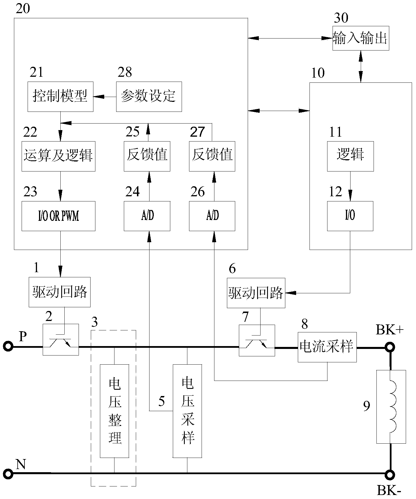
[0084] see Figure 5 , which shows the architecture diagram of the control system provided in this example. It can be seen from the figure that this example makes full use of the existing system of the elevator. The switch control unit 10 in the scheme is placed in the elevator logic control MCU, and the power adjustment control unit 20 is placed in the motor control MCU (DSP). The IGBT module serves as the turn-off electronic switch 2 and the turn-off electronic switch 7 in the scheme.
[0085] The P terminal of the inverter DC bus is connected to the upper end of the IGBT, the current sampling unit 8 is connected to the lower end of the IGBT, the positive end of the voltage adjustment circuit 3 and the voltage sampling unit 5 are connected to the middle end of the IGBT, and the N terminal of the inverter DC bus Connect to the negative terminal of voltage adjustment 3 and voltage detection 5. The rest of the solutions are the same as above, and will not be repeated here.
...
example 2
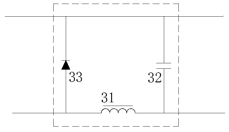
[0093] see Image 6 , which shows the architecture diagram of the control system provided in this example. It can be seen from the figure that in this example, the switch control unit 10, the power adjustment control unit 20, the drive circuit 1 and the drive circuit 6 are placed on an independently arranged PCB, and separate IGBTs are adopted.
[0094] Among them, the rectified P terminal is connected to the upper end of the IGBT 2, the lower end of the IGBT 2 is connected to the voltage adjustment circuit 3, the voltage adjustment circuit 3 is connected to the positive end of the voltage sampling unit 5 and the upper end of the current sampling unit 8, and the current sampling unit The lower end of 8 is connected to the upper end of IGBT 7, the voltage adjustment circuit 3 is connected to the negative end of the voltage sampling unit 5, and the voltage adjustment circuit 3 is connected to the N end of the rectified power supply.
[0095] The control system thus formed, when...
PUM
 Abstract
Description
Claims
Application Information