Single-column hydraulic movable lifter

A mobile lift technology, applied in the field of lifts, can solve the problems of inconvenient movement and large area occupied by lifts, and achieve the effects of simple structure, convenient movement and wide selection range

Inactive Publication Date: 2014-12-17
上海欧珀机电设备有限公司
View PDF5 Cites 5 Cited by
  • Summary
  • Abstract
  • Description
  • Claims
  • Application Information

AI Technical Summary

Problems solved by technology

[0006] The purpose of the present invention is to solve the defects in the prior art that the car lift occupies a large area and is inconvenient to move, and provides a single-column hydraulic mobile lift to solve the above problems

Method used


Image

  • Single-column hydraulic movable lifter
  • Single-column hydraulic movable lifter
  • Single-column hydraulic movable lifter

Examples


Embodiment

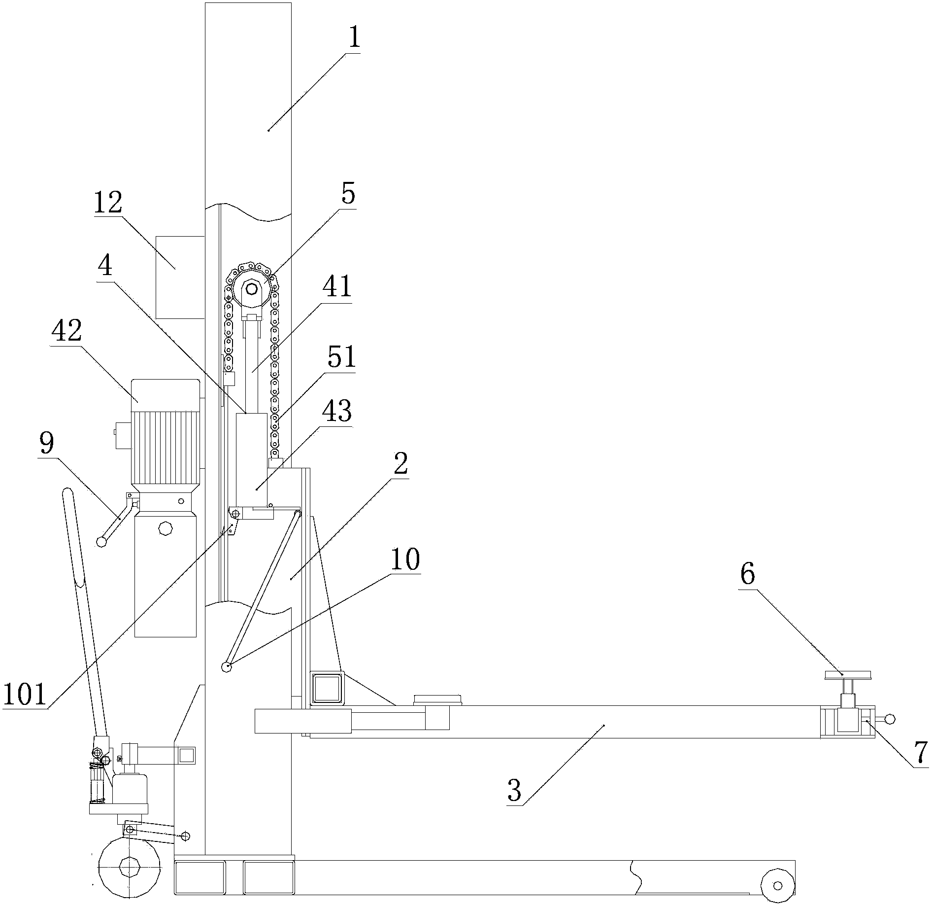
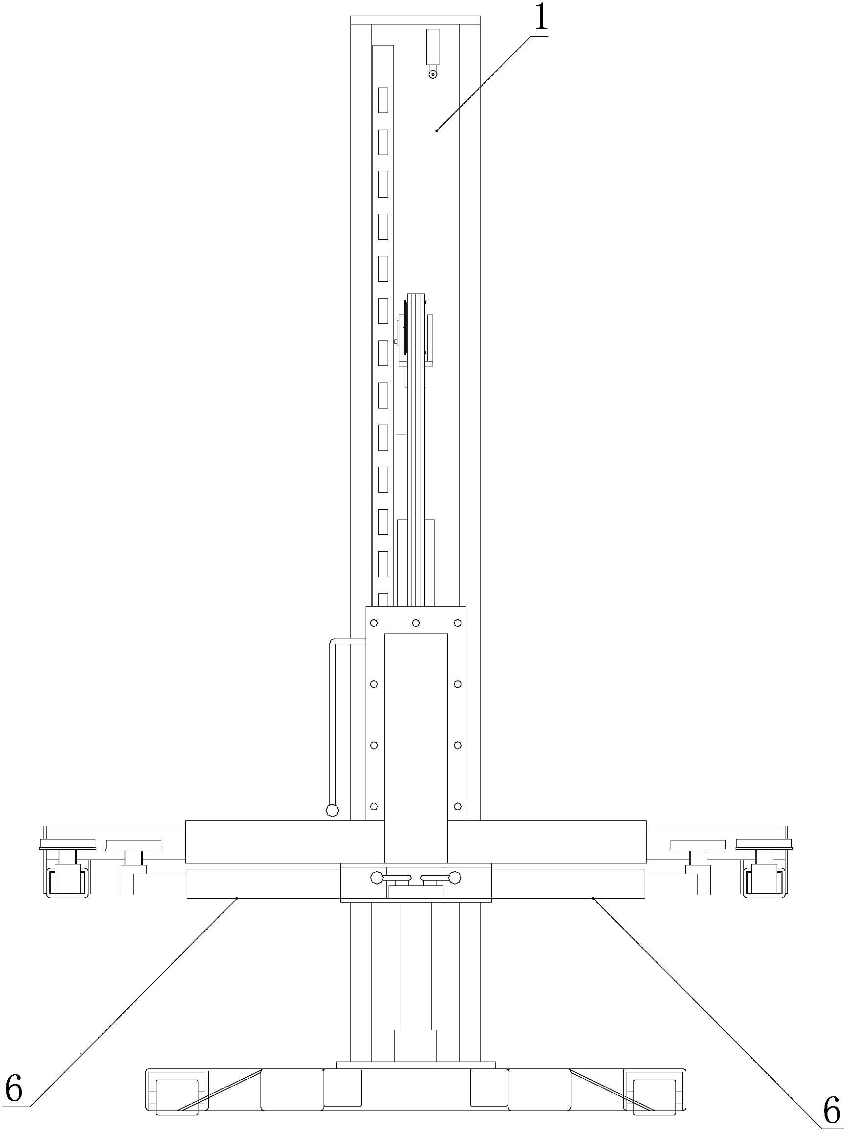
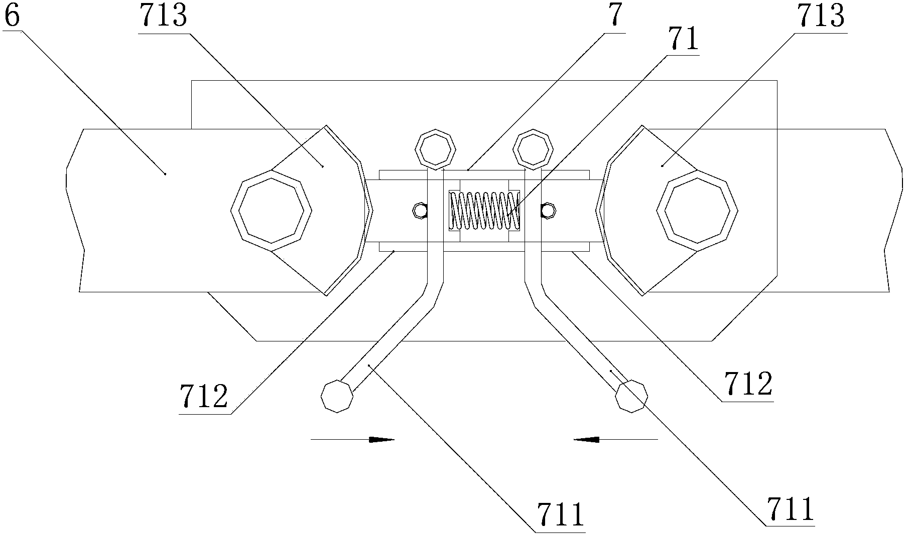
[0030] like figure 1 -6, figure 1 is a structural schematic diagram of the present invention; figure 2 for figure 1 right view of image 3 is a schematic diagram of the structure of the arm locking device; Figure 4 is an exploded view of the arm locking device; Figure 5 is a schematic diagram of the structure of the sprocket and chain;

[0031] Figure 6 It is a schematic diagram of the structure of the safety lock on the tackle.

[0032] A single-column hydraulic mobile lift, comprising a column 1, a trolley 2 is arranged on the column 1, a lifting arm 3 and a hydraulic lifting device 4 with a piston rod 41 are arranged on the trolley 2, and the bottom of the hydraulic cylinder 43 is connected to the hydraulic pump through the oil pipe. Station 42 is connected, and a sprocket 5 is set on the top of the piston rod 41 extending out of the hydraulic cylinder, and a lifting chain 51 is set on the sprocket 5. The first end of the lifting chain 51 is fixed on the column 1...


PUM


Abstract

The invention discloses a single-column hydraulic movable lifter. The single-column hydraulic movable lifter comprises a vertical column. A tackle is arranged on one side of the vertical column, a lifting arm is arranged on the tackle, a hydraulic cylinder with an upward piston rod is arranged in an inner cavity of the vertical column, the top end of the portion, stretching out of the hydraulic cylinder, of the piston rod is provided with a chain wheel, a lifting chain is arranged on the chain wheel, the first end of the lifting chain is fixed to the vertical column, and the second end of the lifting chain is connected with the tackle. By the adoption of the single-column movable lifter, the occupied area of a workplace is reduced; a manual pallet jack is arranged at the lower end of the vertical column and has multiple purposes; the lifter can also serve as a parking device of a household garage; a hydraulic lifting device provides power, so that the selection range of power sources is wide; the lifter can work in field environments without power sources; the lifter is simple in structure and very practical.

Description

technical field [0001] The invention relates to the technical field of lifts, in particular to a single-column hydraulic mobile lift. Background technique [0002] The hydraulic lifting device uses liquid as the working medium to transmit power through the piston rod. Hydraulic pressure is widely used in industrial and civil industries due to its large transmission force, easy transmission and configuration. The function of the hydraulic cylinder and the hydraulic motor, the actuators of the hydraulic system, is to convert the pressure energy of the liquid into mechanical energy to obtain the required linear reciprocating motion. [0003] Lifts are often used in the repair and maintenance of the automobile field. It is to lift the car to a certain height, so that maintenance personnel can carry out repair and maintenance work under the car. [0004] The existing lifts are all double-column structures, that is, the two columns are about 3 meters apart. The vehicle enters be...

Claims


Application Information

Patent Timeline
Patent Type & Authority Applications(China)
IPC IPC(8): B66F7/04B66F7/28
Inventor 李黎明
Owner 上海欧珀机电设备有限公司
Why Eureka
Try Eureka