Shear wall corner replaceable energy dissipation component and energy dissipation structure
What is Al technical title?
Al technical title is built by PatSnap Al team. It summarizes the technical point description of the patent document.
A shear wall and energy dissipation technology, applied in the direction of walls, building components, building structures, etc., can solve the problem of low stiffness of viscous dampers or friction energy dissi The stiffness of the force wall is reduced and other problems, so as to achieve the effect of good ductility, easy popularization and application, and recovery of the seismic function.
Active Publication Date: 2014-12-17
TONGJI UNIV
View PDF9 Cites 11 Cited by
Summary
Abstract
Description
Claims
Application Information
AI Technical Summary
This helps you quickly interpret patents by identifying the three key elements:
Problems solved by technology
Method used
Benefits of technology
Problems solved by technology
[0004] The compressive bearing capacity of general concrete wall pieces is about 3-5 times of the tensile bearing capacity, and the existing energy dissipators or tensile bearings all have the phenomenon that the stiffness or bearing capacity does not match the shear wall, for example: The stiffness of the hysteresis damper or the frictional energy dissipator is too small; the tensile and compressive bearing capacity of the metal type energy dissipator or the anti-buckling support is basically equal, which does not match the characteristic that the compressive resistance of the concrete shear wall is much greater than the tensile bearing capacity; the soft steel rubber The support is made of rubber, which will cause a significant decrease in the stiffness of the shear wall
Method used
Image
Click on the blue label to locate the original text in one second.
Reading with bidirectional positioning of images and text.
Examples
Embodiment Construction
[0041] The present invention will be further described below in conjunction with the embodiments shown in the accompanying drawings.
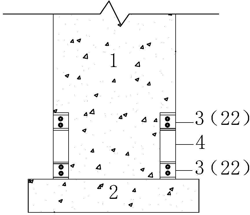
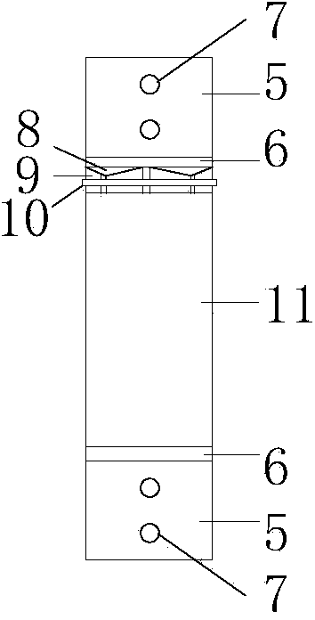
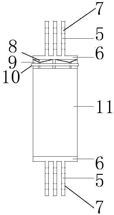
[0042] like Figure 1 to Figure 3 As shown, the present invention discloses a replaceable energy-dissipating component at the foot of a shear wall, which includes connecting sections 3 at the upper and lower ends and a main body section 4 in the middle.
[0043] Among them, such as Figure 2 to Figure 4As shown, the connecting sections respectively include connecting end plates 6 and energy-dissipating connectors for connecting with the shear wall. The specific structure of the energy-dissipating connectors can be set according to specific conditions. In this embodiment, the energy-dissipating connectors include The connecting guide rail 5 and the connecting guide rail bolt hole 7 are fixedly arranged on one end surface of the connecting end plate 6 , and the connecting guide rail bolt hole 7 is provided through the connecting guide rail 5 . ...
PUM
Abstract
The invention provides a shear wall corner replaceable energy dissipation component, which comprises connecting sections and a main body section, wherein the connecting sections are arranged at the upper and lower ends, the main body section is arranged in the middle, the connecting sections are used for connecting a shear wall, the main body section comprises a steel pipe concrete section and a pre-tightening self filling section, the steel pipe concrete section comprises a pressure-resistant steel plate, steel pipes, concrete and an anti-bending inner core, the pressure-resistant steel plate is positioned at the upper part, the steel pipes are positioned on the periphery and are used as outer walls, the concrete and the anti-bending inner core are positioned at the inside, the pre-tightening self filling section comprises an inclined steel supporter, a plurality of pressure-resistant steel gaskets and a pre-tightening coil, when being pulled, the anti-bending inner core and the steel pipe concrete are disconnected, the steel pipe concrete cannot be damaged through pulling, and the pre-tightening self filling section can automatically fill gaps formed through pulling, so when being reversely stressed, the steel pipe concrete can immediately receive the force, the anti-bending inner core and the steel pipe concrete simultaneously bear the pressure, through the design, the damage of the shear wall can be concentrated on the replaceable component, and in addition, the shear wall corner replaceable energy dissipation component and the shear wall are detachably connected, so the anti-seismic function of the shear wall can be fast recovered through replacing the replaceable component after an earthquake.
Description
technical field [0001] The invention belongs to the technical field of buildings, and relates to an anti-shock and shock-absorbing technology, in particular to an anti-shock and shock-absorbing technology for a reinforced concrete shear wall of a high-rise building structure. Background technique [0002] Earthquakes will not only cause direct economic losses, but also cause indirect economic losses such as temporary stop or reduction of production, disturbance of the original balanced economic system, or reduction of external investment. Past earthquake damage experience shows that the indirect economic losses of earthquake disasters around the world Losses often go beyond direct economic losses. [0003] As one of the most widely used lateral force structures in high-rise structures, reinforced concrete shear walls play an important role in seismic fortification. In high-rise structures, the main function of reinforced concrete shear walls is to provide greater stiffness a...
Claims
Application Information
Patent Timeline
Application Date:The date an application was filed.
Publication Date:The date a patent or application was officially published.
First Publication Date:The earliest publication date of a patent with the same application number.
Issue Date:Publication date of the patent grant document.
PCT Entry Date:The Entry date of PCT National Phase.
Estimated Expiry Date:The statutory expiry date of a patent right according to the Patent Law, and it is the longest term of protection that the patent right can achieve without the termination of the patent right due to other reasons(Term extension factor has been taken into account ).
Invalid Date:Actual expiry date is based on effective date or publication date of legal transaction data of invalid patent.