
A downhole steam injection pipe string for heavy oil thermal recovery well

A heavy oil thermal recovery and steam pipe technology, which is applied in wellbore/well components, production fluid, earthwork drilling and production, etc., can solve the problem of poor steam injection effect in oil layers, failure to achieve viscosity reduction production, wellhead casing head leakage, etc. problems, to achieve the effect of increasing the oil-steam ratio, improving the effect of steam injection, and improving the quality of steam injection

Active Publication Date: 2016-09-21
CHINA PETROLEUM & CHEM CORP +1
View PDF5 Cites 0 Cited by
  • Summary
  • Abstract
  • Description
  • Claims
  • Application Information

AI Technical Summary

Problems solved by technology

But at the same time, if the steam injection pressure difference is 15Mpa, the upward force generated by the pressure difference acting on the thermal packer also reaches 300KN. Since the thermal packer has no fixed anchoring device, the relative up and down of the thermal packer and the casing Sliding release, its seal is damaged, causing steam to leak into the casing above the thermal packer, and conduct to other formations, resulting in a large loss of heat energy, damage to the casing, and easily cause leakage of the casing head at the wellhead , leading to poor steam injection effect in the oil layer, failing to achieve the purpose of viscosity reduction production

Method used


Image

  • A downhole steam injection pipe string for heavy oil thermal recovery well
  • A downhole steam injection pipe string for heavy oil thermal recovery well
  • A downhole steam injection pipe string for heavy oil thermal recovery well

Examples


Embodiment Construction

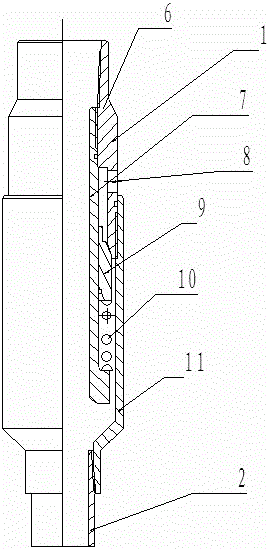
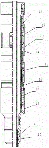
[0012] The present invention is described in detail below in conjunction with accompanying drawing, see figure 1 , figure 2 and image 3 A downhole steam injection string in a heavy oil thermal recovery well includes a thermal insulation tube and a suspension packer 3, the thermal insulation tube, a backwash valve 1 and a sealed telescopic tube 2 are sequentially connected to form an inner steam injection string; the suspension packer 3 is sequentially connected with the sealing sleeve 4 and the switch assembly 5 to form the steam injection outer pipe string; the suspension packer 3 of the steam injection outer pipe string is seated and suspended on the inner wall of the casing, and the sealing and expansion of the steam injection inner pipe string The pipe 2 is inserted into the switch assembly 5 of the steam injection outer column and can slide in the sealing sleeve 4 . The sealing telescopic tube 2 includes a sliding tube and a clamp claw 23, and the upper part of the sl...


PUM


Abstract

The invention discloses a downhole steam injection pipe string in a heavy oil thermal recovery well, which can protect the casing in the steam injection well, improve the steam dryness at the bottom of the well, and improve the thermal efficiency and steam injection effect of steam injection. The steam injection pipe string includes heat insulation pipe and suspension packer, heat insulation pipe, backwash valve and sealing telescopic pipe are sequentially connected to form the steam injection inner pipe string; suspension packer is sequentially connected with sealing sleeve and switch assembly to form The steam injection outer string; the suspension packer of the steam injection outer string is seated and suspended on the inner wall of the casing, and the sealed telescopic tube of the steam injection inner string is inserted into the switch assembly of the steam injection outer string and can be Sliding in the sealing sleeve. The invention can realize one-time decentralization and multiple use, the quality of steam injection is obviously improved, the oil-gas ratio is improved, and the oil-increasing effect is obvious. The pipe string of the present invention has simple structure, reliable operation, improved steam sweep volume and multi-round steam injection efficiency, fully saves energy, effectively protects the casing, and eliminates the leakage of the casing head at the wellhead of the existing steam injection pipe string. disadvantages.

Description

technical field [0001] The invention belongs to the downhole steam injection pipe string of the petroleum industry, in particular to a downhole steam injection pipe string of a heavy oil thermal recovery well, which can protect the casing in the steam injection well, improve the dryness of the steam at the bottom of the well, improve the thermal efficiency and steam injection efficiency of steam injection. Effect, save energy, improve oil-gas ratio. Background technique [0002] Due to the high viscosity of heavy oil reservoirs, it is not easy to flow. How to pump it from the formation to the wellbore, and then lift it from the wellbore to the surface is a relatively difficult problem. Injecting steam into the oil layer to reduce its viscosity is the most commonly used and most effective method at present. However, the oil layer is one to two thousand meters deep underground. During the process of injecting steam into the oil layer with a pipe string from the surface, if th...

Claims


Application Information

Patent Timeline
Patent Type & Authority Patents(China)
IPC IPC(8): E21B43/24
Inventor 杜勇谢金川钱钦候利邹群周志超
Owner CHINA PETROLEUM & CHEM CORP
Learn More