Ultra-thin LED lamp and production technology thereof

A technology of LED lighting and production technology, applied in the field of lighting, can solve problems such as poor light distribution, easy to produce dark shadows, and dark areas with large distances from lamp holders, etc., and achieve sufficient and effective heat dissipation

Inactive Publication Date: 2014-12-17
郭华忠
View PDF8 Cites 5 Cited by
  • Summary
  • Abstract
  • Description
  • Claims
  • Application Information

AI Technical Summary

Problems solved by technology

And install light-emitting diode lamp beads to solve the problem that the current light-emitting diode (LED lamp) has a large distance from the lamp holder to the light-emitting surface due to its large heat dissipation.
Obviously, the above two patent structures are based on how to improve the heat dissipation efficiency of LED lamps, and do not improve the structure in combination with the efficiency of LED lamps, resulting in low light efficiency, uneven illumination, easy to produce dark shadows, black circles, etc. poor light phenomenon

Method used


Image

  • Ultra-thin LED lamp and production technology thereof
  • Ultra-thin LED lamp and production technology thereof
  • Ultra-thin LED lamp and production technology thereof

Examples


Embodiment 1

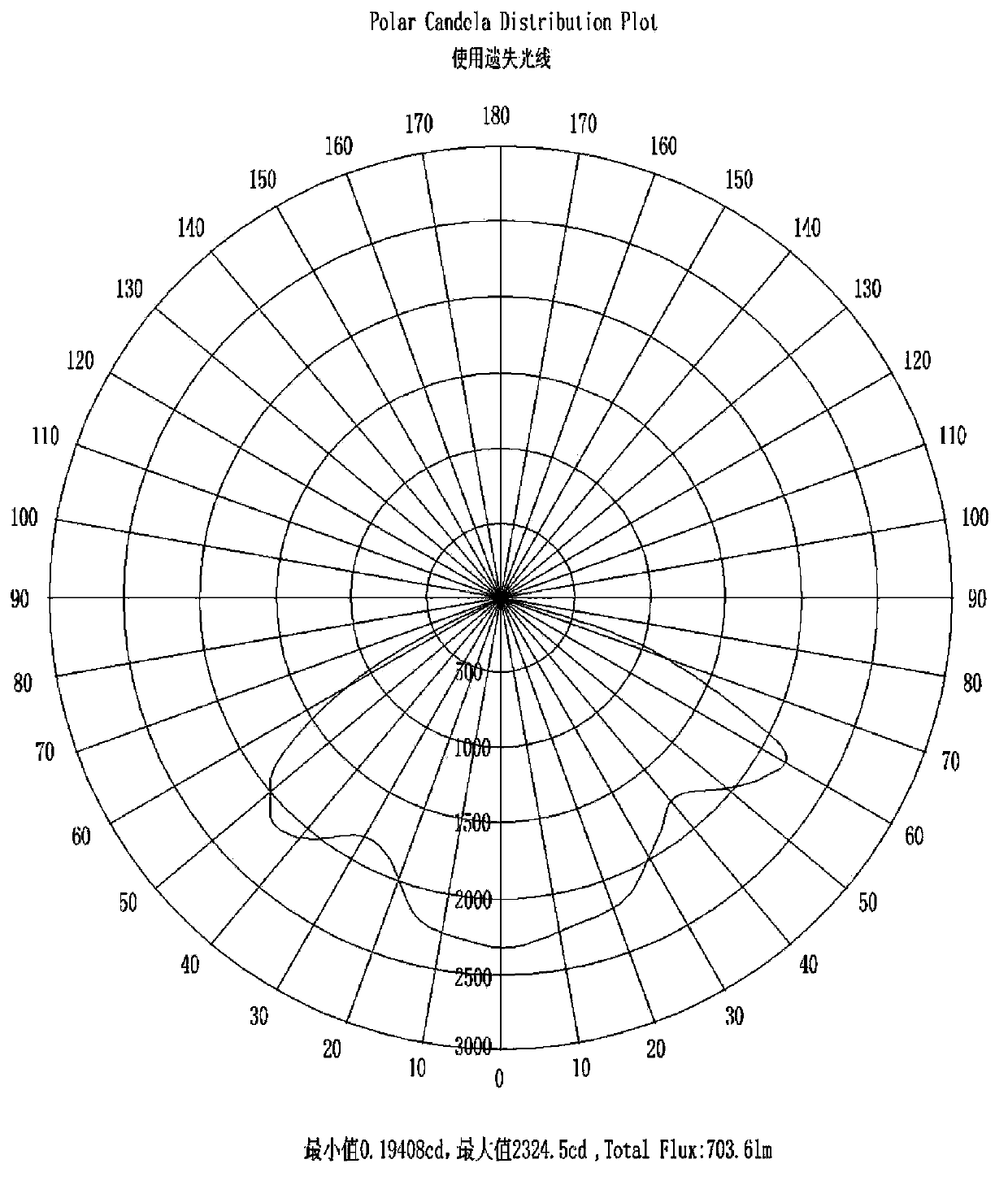
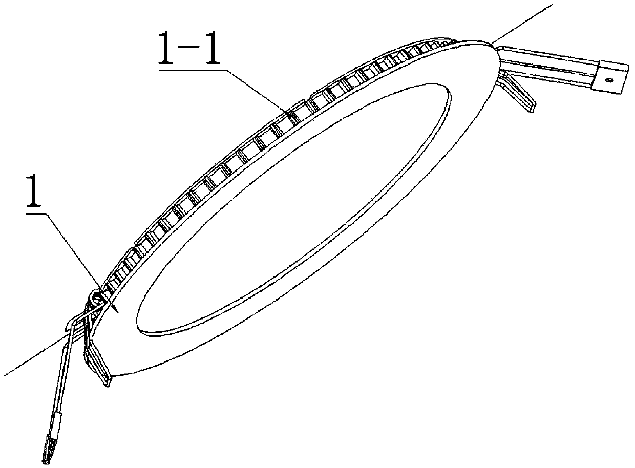
[0041] Such as figure 1 As shown, the present invention is an ultra-thin LED lamp, which includes a heat dissipation lamp body 1 with a light emitting surface, a back cover 2 connected and matched with the heat dissipation lamp body 1, and a back cover 2 arranged between the heat dissipation lamp body 1 and the back cover 2 The diffuser plate 3, the light guide plate 5, and the reflective paper 6 are arranged sequentially from bottom to top. The outer cover of the light guide plate is provided with a flexible LED substrate 4, and LED lamp beads are evenly distributed on the circumference of the flexible LED substrate 4. The light guide plate 5 The front side is a high-gloss mirror surface, and the high-gloss mirror surface is facing the diffusion plate. The reverse side of the light guide plate 5 is a convex-concave grid. The light is evenly mixed with forward reflection and diffuse reflection within the required light distribution range, so that the light can be effectively r...

Embodiment 2

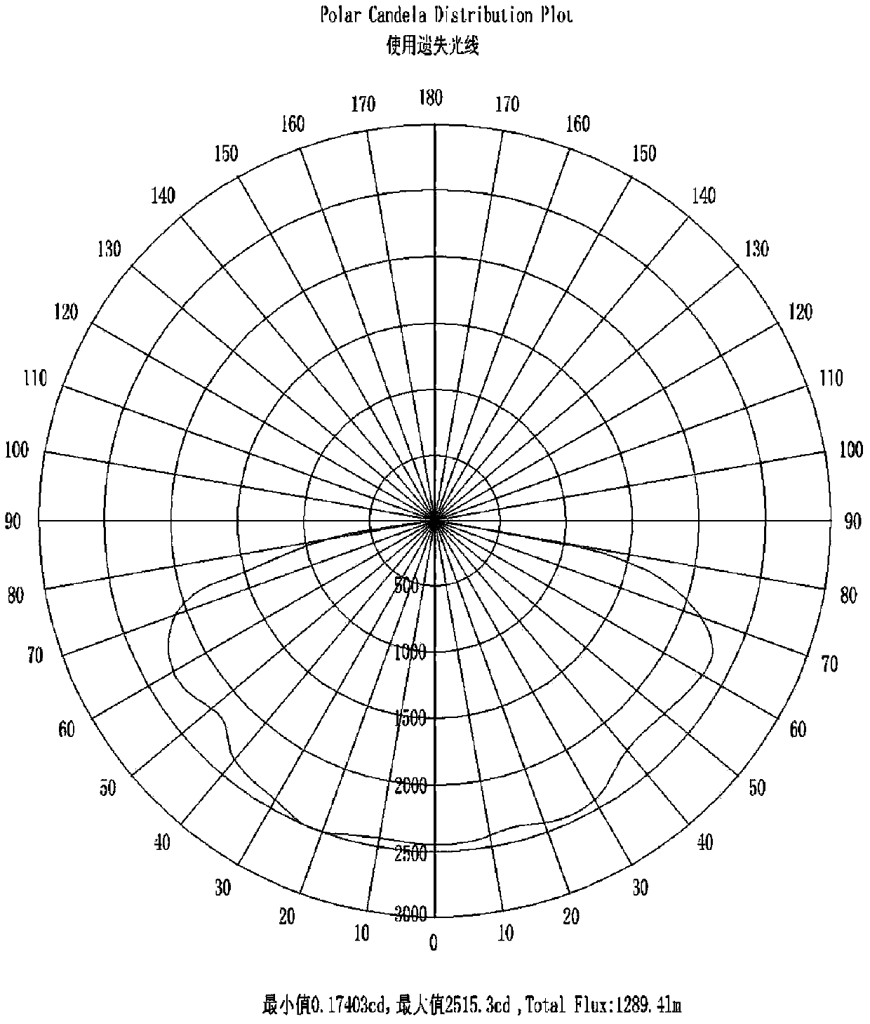
[0053] The difference between this embodiment and the above-mentioned implementation is that the light guide plate and the reflective paper are combined into one, and the specific process is realized: after the mold of the PC light guide plate is injected, the ultra-thin mirror reflective film is pressed on the concave and convex surface of the light guide plate , and its thickness is 0.1mm. Through this production process technology, the light guide plate can complete the effect function of the entire light distribution system, including absorbing enough light from the LED lamp into the light guide plate by relying on the light absorption on the side of the edge; The uneven grid realizes the diffuse reflection of the light emitted to the front; the light overflowed by a very small amount in the diffuse reflection passes through the ultra-thin mirror reflective film on the back of the light guide plate, and after the light is diffusely reflected in the forward direction again, ...


PUM


Abstract

The invention discloses an ultra-thin LED lamp and a production technology thereof. The LED lamp is characterized in that a radiating lamp body, a rear cover plate, a diffusion plate and a light guide plate are included, the radiating lamp body is provided with a light-emitting face, the rear cover plate is connected and matched with the radiating lamp body, the diffusion plate and the light guide plate are sequentially arranged between the radiating lamp body and the rear cover plate from bottom to top, the light guide plate is sleeved with a flexible LED substrate, the periphery of the flexible LED substrate is evenly provided with LED lamp beads, the front side of the light guide plate is a highlight mirror corresponding to the diffusion plate, the back side of the light guide plate is an uneven grid, and the difference of convex and concave sections is 0.05-0.3 mm. The LED lamp is low in cost, a few of materials are used, production and assembly are easy, the light guide plate has various light reflection functions to meet various requirements of light distribution, LED light rays are fully used, light loss is reduced to the minimum, the whole LED lamp is low in weight, and the aim of miniaturization is achieved.

Description

technical field [0001] The invention relates to the technical field of lighting, and more specifically relates to an LED lamp and a production process thereof. Background technique [0002] Luminaire efficiency refers to the ratio of the luminous flux value emitted by the luminaire measured under specified conditions to the sum of the measured luminous flux values ​​emitted by all light sources in the luminaire. In order to improve the efficiency of the existing LED lamps and improve the heat dissipation effect, the methods adopted by those skilled in the art, such as the patent application number 201120020531.9, and the name of the invention is an ultra-thin flat LED lamp, including a back cover, an LED light source, a power supply and a panel. It is characterized in that the panel is mainly composed of a surface frame, a diffuser plate and a dustproof plate, and the surface frame is a detachable thin-layer frame composed of outer frame strips, inner frame strips and their ...

Claims


Application Information

Patent Timeline
Patent Type & Authority Applications(China)
IPC IPC(8): F21S2/00F21V8/00F21V23/00F21V17/04F21V29/00F21V5/08F21V7/22F21Y101/02
Inventor 王玮梁佩婷蔡和江
Owner 郭华忠
Why Eureka
Try Eureka