A solar cell packaging structure
A technology for solar cells and solar cells, applied in circuits, photovoltaic power generation, electrical components, etc., can solve problems such as reducing the efficiency of solar cells, and achieve the effects of eliminating heat island effect, improving conversion rate, and high utilization rate
- Summary
- Abstract
- Description
- Claims
- Application Information
AI Technical Summary
Problems solved by technology
Method used
Image
Examples
Embodiment 1
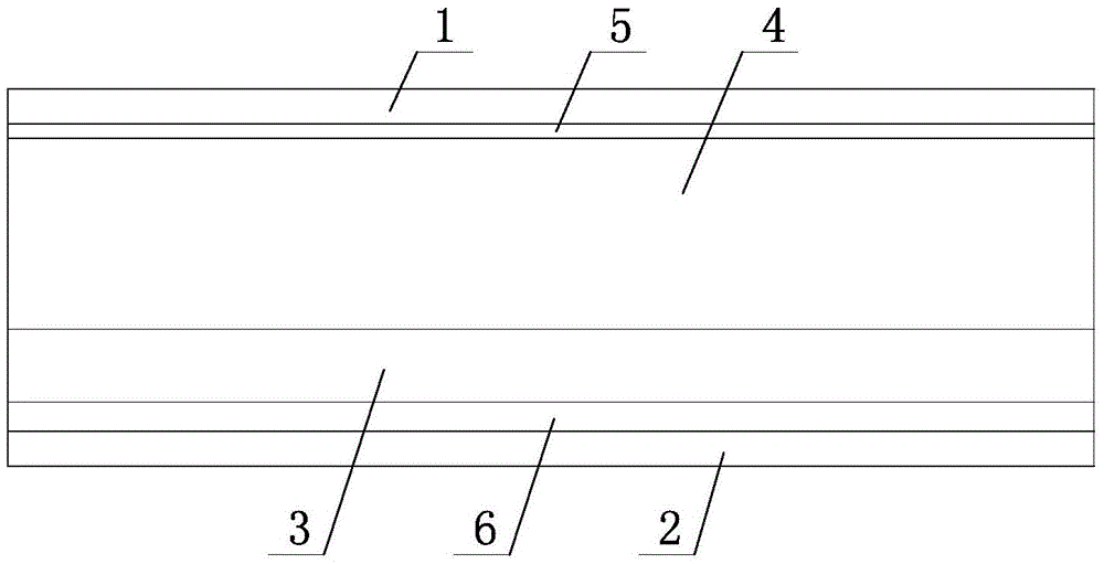
[0023] Such as figure 1 As mentioned above, the solar cell encapsulation structure of this embodiment includes double-layer glass with a cavity 4, unpackaged solar cell slices 3 placed in the cavity 4, and the double-layer glass is formed by front side glass 1 and rear side glass 2. It is formed by sealing and splicing around the double-layer glass. The back of the solar cell 3 is fixed on the inner wall of the rear glass 2. The distance from the light-facing surface of the solar cell 3 to the inner wall of the front glass 1 is 3 cm. Glass 1 is solar white glass with a thickness of 4mm.
[0024] When small particles are present, the incident light is diffracted, eliminating shadows on the solar cell. The solar cell itself is not packaged, so the manufacture of 250W solar modules hardly increases the cost and solves the problem of heat island effect.
[0025] In order to prevent the incoming light from escaping due to reflection, figure 1 In the shown embodiment, the inner s...
Embodiment 2
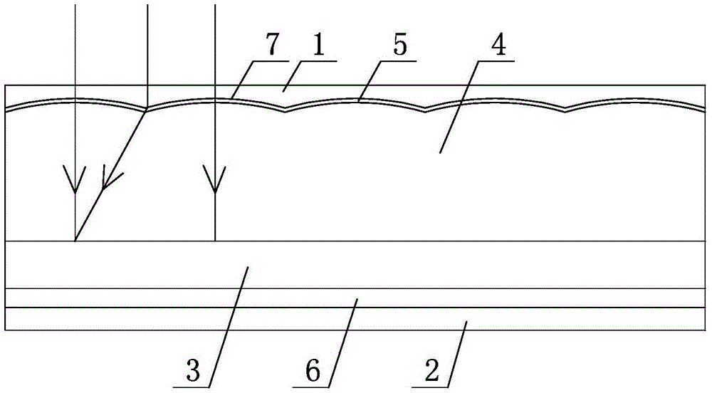
[0028] Such as figure 2 As shown, the main structure of this embodiment is the same as that of Embodiment 1, the difference is that the inner wall of the front side glass 1 is shaped on a strip-shaped depression 7, and the glass at each depression 7 forms a concave lens with a width of 3 cm and a focal length of 3 cm. Such as figure 2 As shown, when the light is vertically incident, the parallel light at the edge of the concave lens can be projected to the center of the solar panel behind the adjacent concave lens. Lines with arrows in the figure represent light rays. For the rest of the symbols in the figure, refer to figure 1 . It can be seen from the figure that the light diverges through the concave lens, so the blocked area will be compensated by the light scattered by the nearby concave lens, thereby eliminating the shadow on the solar cell and preventing the heat island effect.
Embodiment 3
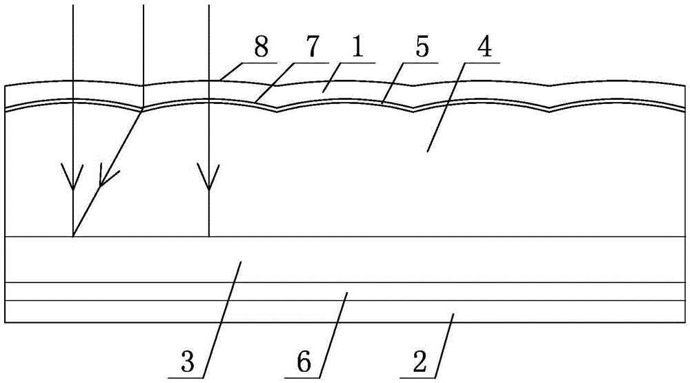
[0030] Such as image 3 As shown, the main structure of this embodiment is the same as that of Embodiment 1, the difference is that the inner wall of the front side glass 1 is formed with a strip-shaped arc-shaped depression 7, and the corresponding position on the outside is formed with a strip-shaped arc-shaped protrusion 8, and each depression 7 and The protrusion 8 forms a concave lens with a width of 3 cm and a focal length of 3 cm. Such as image 3 As shown, when the light is vertically incident, the parallel light at the edge of the concave lens can be projected to the center of the solar panel behind the adjacent concave lens. Lines with arrows in the figure represent light rays. For the rest of the symbols in the figure, refer to figure 1 .
[0031] The principle of this embodiment is the same as that of Embodiment 2, and the further improvement is that the front side glass 1 is made into a shape with wavy protrusions, so that when the leaves fall on the front sid...
PUM
 Abstract
Description
Claims
Application Information
 - R&D
- Intellectual Property
- Life Sciences
- Materials
- Tech Scout
- Unparalleled Data Quality
- Higher Quality Content
- 60% Fewer Hallucinations
Browse by: Latest US Patents, China's latest patents, Technical Efficacy Thesaurus, Application Domain, Technology Topic, Popular Technical Reports.
© 2025 PatSnap. All rights reserved.Legal|Privacy policy|Modern Slavery Act Transparency Statement|Sitemap|About US| Contact US: help@patsnap.com


