Juicer

A juicer and drive mechanism technology, applied in the field of kitchen utensils, can solve problems such as increased product manufacturing costs, easy cracking of the shell, noise, etc., to achieve the effects of saving manufacturing and transportation costs, reducing product volume, and reducing manufacturing costs

Active Publication Date: 2016-08-10
FORTUNE TECH MFG CO LTD
View PDF5 Cites 0 Cited by
  • Summary
  • Abstract
  • Description
  • Claims
  • Application Information

AI Technical Summary

Problems solved by technology

The major disadvantages of this method of juicing are: due to the relatively large noise and vibration during the high-speed operation of the juicer, it produces a lot of noise to the operating environment, and in addition, the inherent taste in the food during the high-speed juicing process and nutrition are also severely damaged
Although this kind of juicing method solves the noise problem and keeps the inherent taste and nutrition in the food from being lost, it has the following disadvantages: First, this kind of juicing method mainly utilizes the rotary extrusion torque between the screw and the inner wall of the shell to squeeze the food Crushing and grinding, so the required torque is relatively large, and only high-torque motors can be used, which increases the manufacturing cost of the juicer; moreover, the concentrated torque on the side of the shell is too large, and the shell is easy to crack after long-term use, which shortens the life of the machine. Short; Secondly, in order to ensure sufficient grinding in this way of juicing, the length of the juicer head should not be too short, resulting in a higher height of the shell, which increases the manufacturing cost of the product on the one hand, and is inconvenient for users to operate on the other hand; This kind of juicing method is difficult to cut off the fiber in the food. When encountering high-fiber food, it is easy to block the filter, resulting in insufficient juice production.

Method used


Image

  • Juicer
  • Juicer
  • Juicer

Examples


Embodiment Construction

[0047] The present invention will be described in detail below with reference to the accompanying drawings and examples. It should be noted that, in the case of no conflict, the following embodiments and features in the embodiments can be combined with each other.

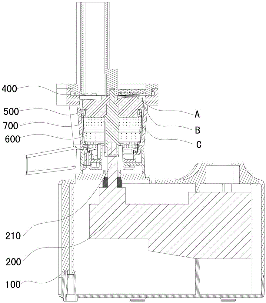
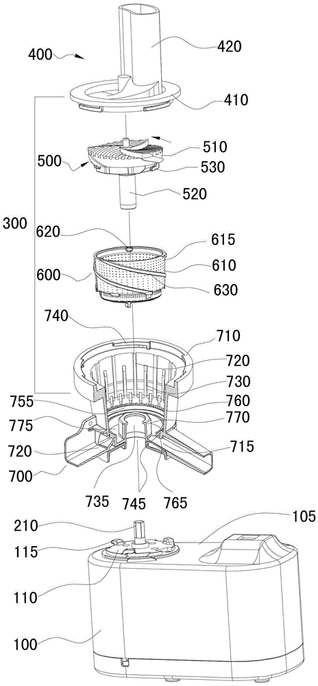
[0048] figure 1 and figure 2 Shown is a schematic structural view of the juice extractor in one of the embodiments of the present invention, the juice extractor includes: a base 100, a drive mechanism 200 and a juice extraction component 300, wherein the top surface 105 of the base 100 has a structure for installing the juice extraction component The support surface 110 of 300 is provided with three buckles 115 arranged along the circumferential direction on the support surface 110 . The driving mechanism 200 shown is installed in the base 100 , and the output shaft 210 of the driving mechanism 200 protrudes from the through hole in the middle of the supporting surface 110 .

[0049] continue to see figure 1 a...


PUM


Abstract

The invention discloses a juice extractor, comprising: a base; a driving mechanism installed in the base; a juice extracting part supported and fixed on the base; the juice extracting part includes: a shell with an opening at the top, a juice outlet and a residue outlet The first grinding disc is rotatably installed in the shell, the first grinding disc includes a first grinding disc main body part and a drive mechanism connection part, the first grinding disc main body part has a first grinding surface, and a second grinding surface is arranged on the first grinding surface A grinding tooth; a second grinding disc, fixedly installed in the housing, the second grinding disc includes a second grinding disc main body, the second grinding disc main body has a second grinding surface, and the second grinding surface is opposite to the first grinding surface, in The second grinding surface is provided with second grinding teeth and a feeding port for food to enter; and a filtering device for separating vegetable juice and pressing residue. The juice extractor of the present invention has the remarkable advantages of low cost, long service life, fast juice output speed, and the filter holes on the filter device are not easy to be blocked.

Description

technical field [0001] The invention relates to kitchen utensils, in particular to a juice extractor capable of extracting juice from vegetables and fruits or extracting soybean milk from beans. Background technique [0002] The juicing mode of existing juice extractor mainly contains following two kinds: [0003] The first is high-speed cutting and centrifugal drying to extract juice. This way of extracting juice is to use a crushing device to crush the fruits and vegetables to be squeezed, and then use centrifugal force to shake out the juice in a high-speed rotation mode. The major disadvantages of this method of juicing are: due to the relatively large noise and vibration during the high-speed operation of the juicer, it produces a lot of noise to the operating environment, and in addition, the inherent taste in the food during the high-speed juicing process And nutrition is also severely damaged. [0004] The second is the screw extrusion juicing method, which uses t...

Claims


Application Information

Patent Timeline
Patent Type & Authority Patents(China)
IPC IPC(8): A47J19/00
CPCA47J19/025A47J19/027A47J19/06
Inventor 王冬雷袁富海庞浩
Owner FORTUNE TECH MFG CO LTD
Why Eureka
Try Eureka