Metal pipe fitting positioning drilling edge pulling machine

A technology of metal pipe fittings and side machines, which is applied to other manufacturing equipment/tools, manufacturing tools, etc., can solve problems such as excessive labor, lack of equipment and fixtures, alignment, and drilling difficulties, so as to save labor and fast installation and fixation , mobile light effect

Inactive Publication Date: 2016-08-31
云南省玉溪市佳利太阳能设备有限公司
View PDF7 Cites 0 Cited by
  • Summary
  • Abstract
  • Description
  • Claims
  • Application Information

AI Technical Summary

Problems solved by technology

[0003] In view of the prior art, when processing the through holes on the solar energy upper and lower heat collecting tubes and pulling up the edges of the through holes to form a reinforced welding edge, there is a lack of special equipment and fixtures, and the existing processing technology uses a lot of manpower, and For the problems of alignment and drilling difficulties, the present invention provides a positioning, drilling and edge pulling machine for metal pipe fittings. The drill bit for punching holes on the pipe fittings, the other is an edge drill, which is equipped with an edge head that pulls up the edge of the metal hole. The lifting wheels of the two bench drills are connected together, and a lifting wheel is installed on the lifting wheel. Shared handle, two bench drills are installed on a fixed seat; a fixed frame is fixedly installed on the lifting workbench of the two bench drills, and the upper end of the fixed frame is a track groove, and rollers and positioning frames are installed in the track groove. The frame is composed of a bottom plate and a splint. The bottom plate is installed on the roller in the track groove. One end of the bottom plate is installed with a rotating connecting shaft and a pipe positioning block, and the other end is installed with a slot plate. One end of the splint is installed and connected to the rotating connecting shaft. A locking lever is installed, and the locking lever corresponds to the position of the card slot on the card slot plate. There are multiple sets of tube clips installed above the bottom plate and below the splint. Anti-skid pads are installed on the surface of the tube clips. Pilot hole, the position of the drill hole on the metal pipe corresponds to the position of the pilot hole

Method used


Image

  • Metal pipe fitting positioning drilling edge pulling machine
  • Metal pipe fitting positioning drilling edge pulling machine

Examples


Embodiment

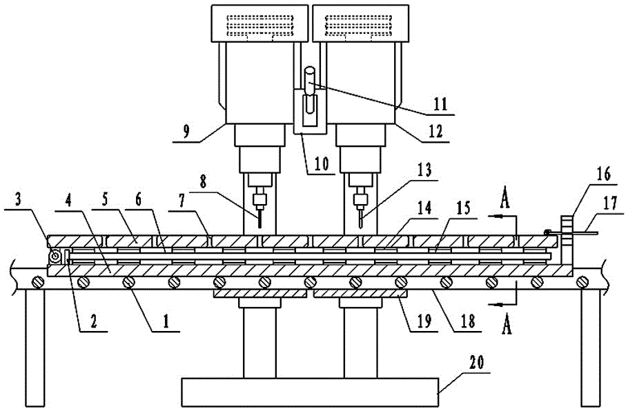
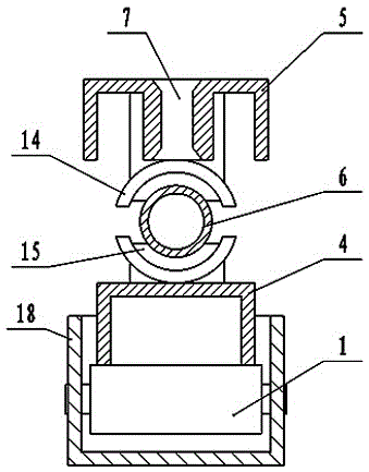
[0007] Example: such as figure 1 and figure 2 As shown, a metal pipe fitting positioning drilling edge pulling machine is formed by two fixed bench drills installed side by side, one of which is a perforating drill 9, and a drill bit 8 for punching holes on the pipe fitting is installed on it. The other is an edge-extracting drill 12, on which an edge-extracting head 13 for pulling up the edge of the metal hole is installed, and the lifting wheels 10 of the two bench drills are connected together, and a shared handle 11 is installed on the lifting wheel 10 , two bench drills are mounted on a fixed seat 20; a fixed frame 18 is fixedly installed on the lifting workbench 19 of the two bench drills, and the upper end of the fixed frame 18 is a track groove, and rollers 1 and positioning are installed in the track groove The positioning frame is composed of a bottom plate 4 and a splint 5. The bottom plate 4 is installed on the roller 1 in the track groove. One end of the bottom ...


PUM


Abstract

The invention relates to a metal pipe fitting positioning drilling and edge-drawing machine, which is formed by installing two fixed bench drills in parallel, wherein one is a drill, and the other is an edge drawing drill; a fixing rack is arranged on workbenches of the two bench drills, and roller wheels and a positioning rack are arranged in a track groove in the upper end of the fixing rack; one end of a bottom plate of the positioning rack is provided with a rotatable connecting shaft and a pipe fitting positioning block, and the other end of the bottom plate of the positioning rack is provided with a slot plate; one end of a clamping plate is arranged on the rotatable connecting shaft, and the other end of the clamping plate is provided with a locking rod; a plurality of groups of pipe clamps are arranged above the bottom plate and below the clamping plate, and guide holes of drill bits are fixedly processed in the clamping plate. With the technology, the two bench drills for drilling and drawing edges are fixed together to complete the drilling and edge drawing works once, so that the labor is greatly saved; due to the track groove and positioning rack design, the positioning rack easily moves on the track groove, cylindrical metal pipes on the positioning rack are quickly installed and fixed, the drilling position is fixed with the guide holes in the positioning rack, the positioning is accurate and quick, and the drilling work efficiency is higher.

Description

technical field [0001] The invention belongs to the technical field of drilling equipment for metal pipe fittings, and relates to a positioning drilling and edge pulling machine for metal pipe fittings. Background technique [0002] On the upper heat collecting tube and the lower heat collecting tube of the flat panel solar heat collector, there are a plurality of through holes, and on the corresponding through holes of the upper heat collecting tube and the lower heat collecting tube, heat collecting fins with headers shall be welded. The through holes on the upper and lower heat collecting tubes are processed with a fixed bench drill. In order to increase the welding firmness between the through holes of the upper and lower heat collecting tubes and the nozzle of the pinnae header, it is necessary to cut the holes of the through holes of the upper and lower heat collecting tubes. Pull up to make a convex round edge appear on the edge of the hole, and the pinna header nozzl...

Claims


Application Information

Patent Timeline
Patent Type & Authority Patents(China)
IPC IPC(8): B23P23/04
CPCB23P23/04
Inventor 雷佳雷兴龙普艳红
Owner 云南省玉溪市佳利太阳能设备有限公司
Why Eureka
Try Eureka