Permanent magnetic adsorbing mechanical arm

A technology of magnetic adsorption and manipulator, which is applied in the direction of manipulators, chucks, manufacturing tools, etc., can solve the problems of high power consumption and high cost of use, and achieve the effect of simple structure, low energy consumption and easy manufacture

Inactive Publication Date: 2014-12-24
苏州格雷特机器人有限公司
6 Cites 10 Cited by

AI-Extracted Technical Summary

Problems solved by technology

When grasping some metal products or metal scraps, an electromagnetic structure is often used at the end of the manipulator to achieve the adsorption of ferrous objects. Although t...

Method used

As shown in Figure 3, described magnetic force module 3 is disc shape, and described small magnetic piece 31 is cylindrical shape, is arranged layer by layer along the plane circumferential direction of described magnetic force module 3 lower; Described limit post 7 is Cylindrical shape, the edge of the lower plane of the magnetic module 3 is processed with a semicircular groove 32 , and the limiting column 7 passes through the semicircular groove 32 . In this way, the small magnetic block 31 can use the marked magnetic block material, and does not need to be specially manufactured, which can effectively reduce the cost. It is also possible to determine the adsorption force generated by the magnetic mod...

Abstract

The invention provides a permanent magnetic adsorbing mechanical arm, comprising an adsorbing box, a lead screw and a magnetic module; the upper part of the adsorbing box connected to the end part of a moving arm is assembled with a rotary motor with a rotary shaft in the vertical direction; the lead screw is fixedly connected to the lower part of the rotary motor and goes deep into the interior of the adsorbing box; the magnetic module is assembled in the adsorbing box; a connection column is fixed on the upper part of the magnetic module; the top of the connection column is assembled with threads of the lead screw; the magnetic module internally wraps a small magnetic block; a limiting column is arranged along the edge of the magnetic module; the lower plane of the adsorbing box is made of a permeability magnetic material. The mechanical arm is simple in structure and easy to manufacture, electromagnetism does not need to be generated by consuming electricity when the mechanical arm is used for carrying objects, the objects are directly adsorbed by using the magnetism of a permanent magnetic material and the energy consumption is greatly reduced.

Application Domain

Technology Topic

Image

  • Permanent magnetic adsorbing mechanical arm
  • Permanent magnetic adsorbing mechanical arm
  • Permanent magnetic adsorbing mechanical arm

Examples

  • Experimental program(1)

Example Embodiment

[0011] In the following, the present invention will be further described in conjunction with the embodiments:
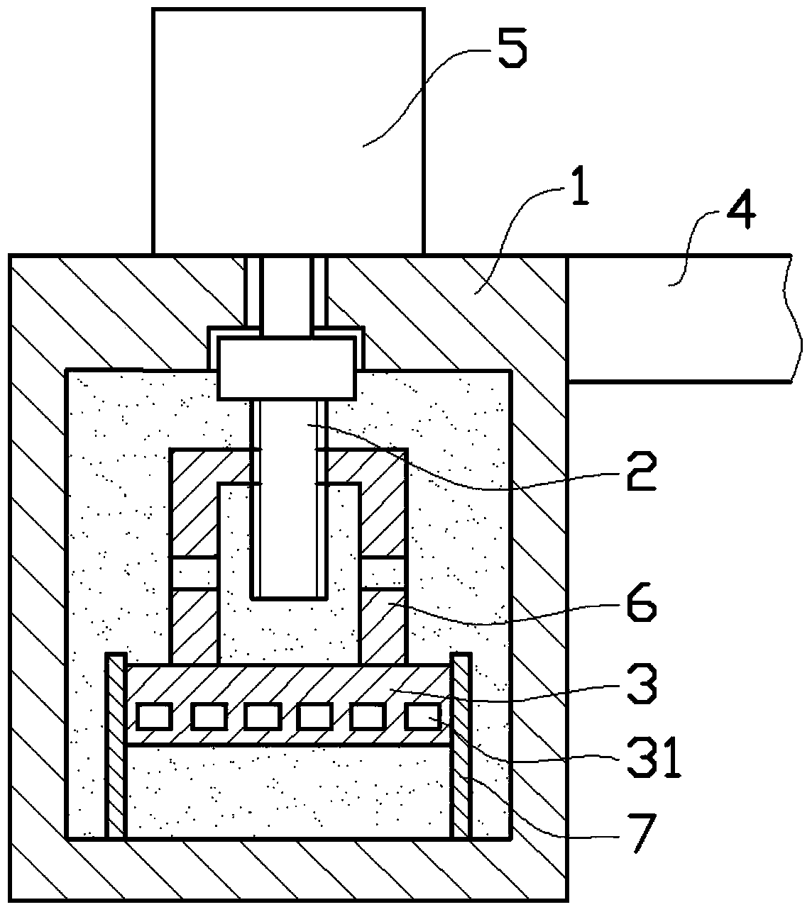
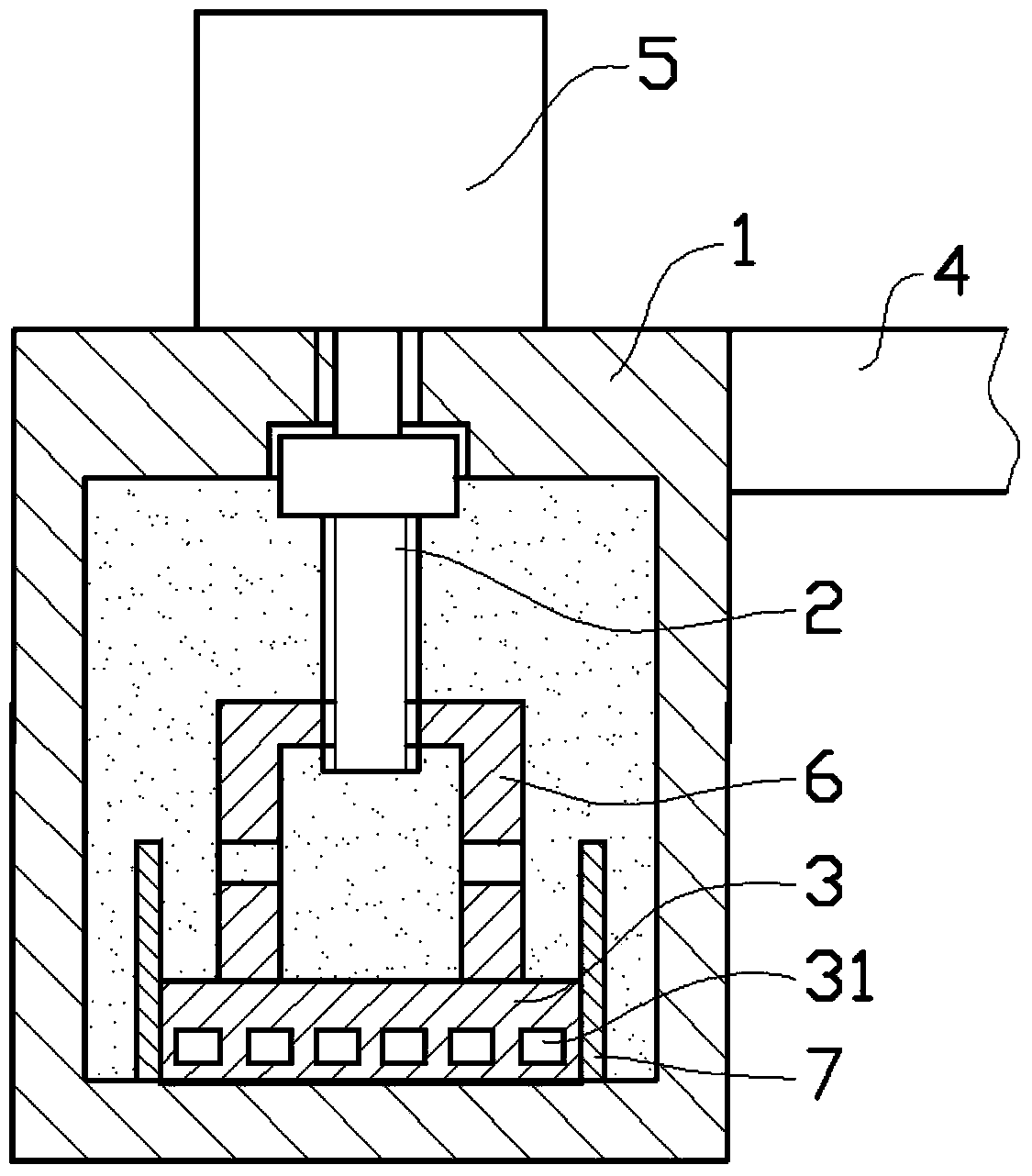
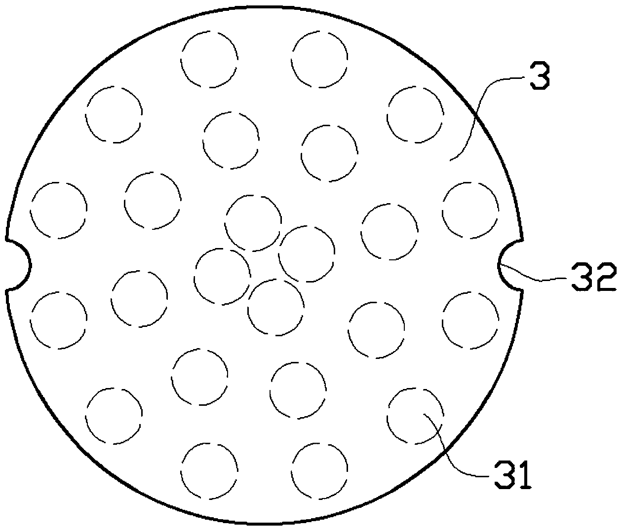
[0012] Such as figure 1 , figure 2 As shown in the embodiment, the permanent magnetic adsorption mechanical arm includes an adsorption box 1, a screw rod 2, and a magnetic module 3. The adsorption box 1 is cylindrical, connected to the end of the moving arm 4 and the upper part of the adsorption box 1. Equipped with a rotating electric machine 5 with a vertical rotating shaft, the rotating output shaft at the lower part of the rotating electric machine 5 is fixedly connected with the screw rod 2 which penetrates into the suction box 1 and the magnetic module 3 is assembled Inside the adsorption box 1, a connecting column 6 is fixed on its upper part. The top of the connecting column 6 is machined with threaded holes for threaded assembly with the screw rod 2, and the magnetic module 3 is wrapped with a small magnet made of permanent magnet material. Block 31, the edge position of the magnetic module 3 is designed with a vertical limit post 7 fixed to the adsorption box 1, and the limit post 7 allows the magnetic module 3 to only move up and down; the adsorption box The lower plane of 1 is made of non-magnetic material. Specifically, the magnetic module 3 and the main body of the adsorption box 1 can be made of aluminum, which has good mechanical properties and is lighter in texture. The adsorption box 1 is connected to the action mechanism through the moving arm 4, which can fulfill the action requirements of the adsorption box 1. The specific shape and structure of the action structure can be specifically designed according to the specific use of the mechanical arm.
[0013] This permanent magnetic adsorption mechanical arm is mainly used to transport ferromagnetic materials. When in use, the lower part of the adsorption box 1 is moved to the upper part of the iron object through the moving arm 4, and the screw 2 is driven by the rotating motor 5 to drive The upper and lower positions of the connecting column 6 and the magnetic module 3 are adjusted so that the lower bottom surface of the magnetic module 3 is attached to the bottom surface of the adsorption box 1. At this time, the small magnetic block 31 in the magnetic module 3 will be magnetic Through the adsorption of the iron object on the bottom surface of the adsorption box 1, the object can be moved to the designed position by the moving arm 4, and then the screw rod 2 is driven by the rotating motor 5 to drive the magnetic module 3 upward. Go, so that the small magnetic block 31 will be far away from the iron object being transported, and the magnetic attraction force will be weakened. Under the action of gravity, the iron object will fall automatically. The mechanical arm has a simple structure and is easy to manufacture. The use of this mechanical arm to transport objects does not need to consume electric energy to generate electromagnetism. The magnetism of the permanent magnetic material is directly used for adsorption, and energy consumption is greatly reduced.
[0014] Such as image 3 As shown, the magnetic module 3 is in the shape of a circular plate, the small magnetic blocks 31 are in the shape of a cylinder, and are arranged layer by layer along the circumferential direction of the lower plane of the magnetic module 3; the limiting column 7 is in the shape of a cylinder, and the magnetic A semi-circular groove 32 is machined at the edge of the lower plane of the module 3, and the limiting column 7 passes through the semi-circular groove 32. In this way, the small magnetic block 31 can use the marked magnetic block material and does not need to be specially manufactured, which can effectively reduce the cost. It is also possible to determine the attraction force generated by the magnetic module 3 by selecting the magnetism of the small magnetic block 31 . At the same time, the small magnetic blocks 31 can be assembled using a mechanism that is easy to disassemble. In this way, the total magnetism generated by the magnetic module 3 can be determined by adjusting the number of the small magnetic blocks 31 in the magnetic module 3.
[0015] Such as figure 1 with figure 2 As shown, the adsorption box 1 is filled with lubricating oil. In this way, the transmission between the screw rod 2 and the connecting column 6 in the adsorption box 1 can be well lubricated, so that the frictional resistance is reduced, more energy saving, and a certain anti-rust effect can be achieved.

PUM

no PUM

Description & Claims & Application Information

We can also present the details of the Description, Claims and Application information to help users get a comprehensive understanding of the technical details of the patent, such as background art, summary of invention, brief description of drawings, description of embodiments, and other original content. On the other hand, users can also determine the specific scope of protection of the technology through the list of claims; as well as understand the changes in the life cycle of the technology with the presentation of the patent timeline. Login to view more.

Similar technology patents

Classification and recommendation of technical efficacy words

  • Simple structure
  • Easy to manufacture

Microlithographic projection exposure apparatus

InactiveUS20050068499A1Simple structureReliable and low-maintenance operationProjectorsPhotomechanical exposure apparatusCamera lensPhysics
Owner:CARL ZEISS SMT GMBH
Why Eureka
Try Eureka