
Dynamic weight measuring method for steel ball mill

A technology of weight measurement and steel ball milling, which is applied in the direction of measuring devices, weighing, and weighing equipment using fluid balance, etc., can solve the problems of steel ball mill dynamic weight measurement, etc., achieve simple methods, improve milling efficiency, and reduce power consumption Effect

Inactive Publication Date: 2014-12-24
SHANGHAI YIFENG ELECTRICAL & MECHANICAL TECH DEV
View PDF5 Cites 0 Cited by
  • Summary
  • Abstract
  • Description
  • Claims
  • Application Information

AI Technical Summary

Problems solved by technology

However, there are no related products and technologies to measure the dynamic weight of steel ball mills

Method used


Image

  • Dynamic weight measuring method for steel ball mill
  • Dynamic weight measuring method for steel ball mill
  • Dynamic weight measuring method for steel ball mill

Examples


Embodiment Construction

[0018] In order to make the present invention more comprehensible, a preferred embodiment is described in detail below with accompanying drawings.

[0019] 1. Establishment of the basic model

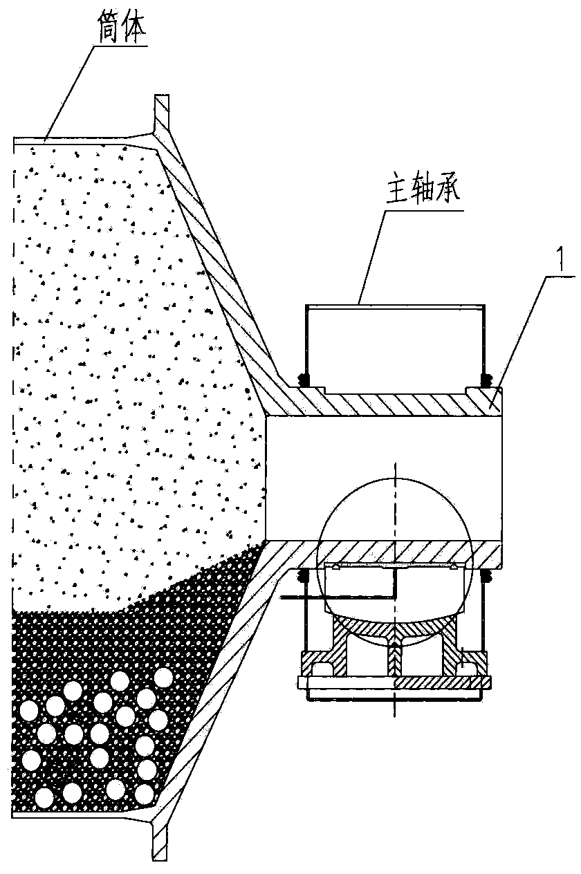
[0020] The present invention requires that the main bearing of the steel ball mill adopts a hydrostatic bearing. combine image 3 , Figure 4 , the hydrostatic bearing can use high-pressure lubricating oil to hold up the entire rotating part of the mill. When the high-pressure oil is injected into the middle of the bearing bush 3, a top grinding high-pressure oil layer 4 is formed on the contact surface between the hollow shaft 1 and the bearing bush 3 of the mill, and the entire rotating part of the mill Suspended above the oil layer. There is a high-pressure sealing ring 2 protruding from the circumference of the contact surface between the bearing bush 3 and the mill hollow shaft 1, so that the oil drain gap is fixed and uniform, and the top grinding area is fixed. This way we ca...


PUM


Abstract

The invention provides a dynamic weight measuring method for a steel ball mill, wherein a B-P function characteristic curve among a cylinder body total weight B (comprising milled object weight and steel ball weight), a high-pressure lubricant pressure P and a contact area S of the steel ball mill can be obtained through establishing a basic model and a true model. According to the high-pressure lubricant pressure P which is measured in real time in operation, the real-time cylinder body weight B can be obtained through reverse computing. The dynamic weight measuring method can conveniently and quickly detect the real-time dynamic weight of the steel ball mill, thereby calculating steel loss weight, obtaining a steel loss curve, and correctly guiding personnel to add steel balls. Simultaneously through comparing the steel loss of steel balls and liner plates which are in different brands or are made of different materials, the dynamic weight measuring method can easily determine which material or brand of the liner plates or steel balls is better. Furthermore a real-time ball to powder ratio can be detected, so that the steel ball mill is always kept in an optimal pulverizing state, thereby greatly improving powder the pulverizing efficiency of the steel ball mill, greatly reducing power consumption of the steel ball mill, and truly realizing energy reduction and production increase.

Description

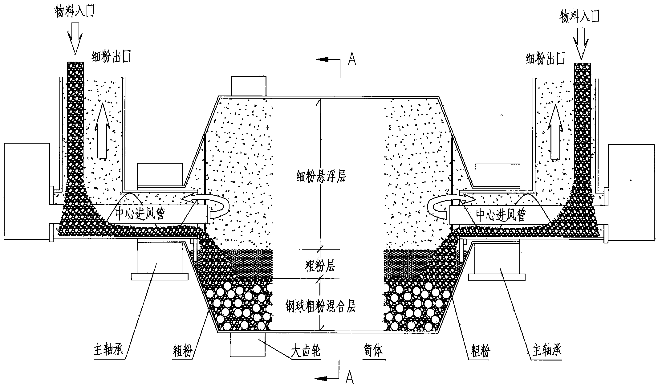
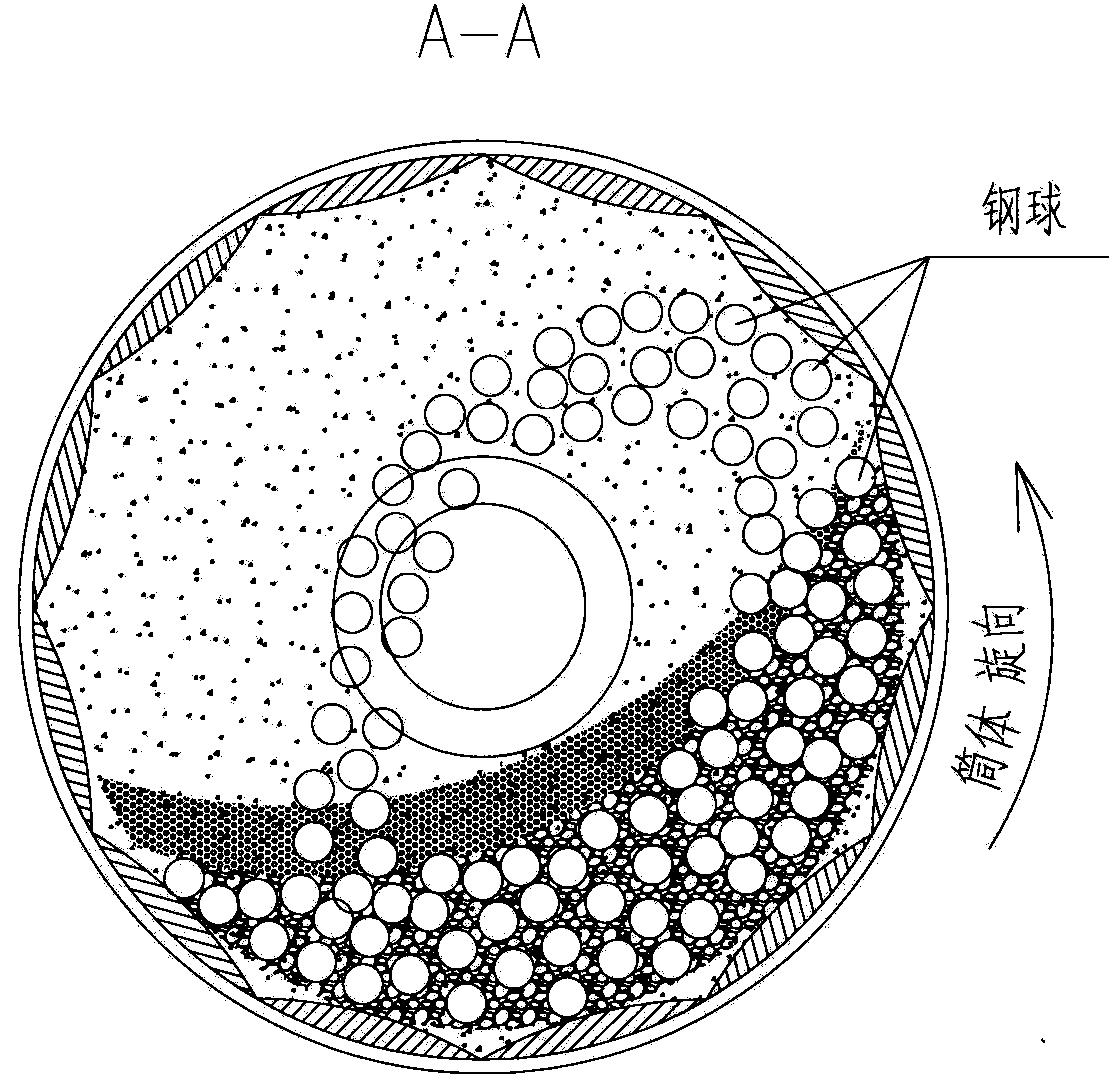
technical field [0001] The invention relates to a dynamic weight measurement method of a cylindrical steel ball mill suitable for the fields of cement, mine and power station pulverizing equipment, and belongs to the technical field of pulverizing equipment weight measurement. Background technique [0002] Cylinder steel ball mills are widely used in cement, mines, and power station enterprises. figure 1 , figure 2 It is the schematic diagram of its basic structure. The cylinder rotates to drive the steel balls to drop, and the materials (cement raw clinker, ore, raw coal, etc.) process. During the operation of the cylindrical steel ball mill, the fine material powder is also output while the large particle material enters, and the steel balls and liners in the mill will also be worn and consumed, so it is necessary to add steel balls regularly. [0003] Steel ball mill is a high-energy-consuming equipment. The cylinder is loaded with tens of tons to hundreds of tons of ...

Claims


Application Information

Patent Timeline
IPC IPC(8): G01G5/00
Inventor 陈刚李大正何锋发
Owner SHANGHAI YIFENG ELECTRICAL & MECHANICAL TECH DEV
Learn More