Test method, test fixture and test device for thin core board layer short risks

A technology of testing device and testing method, which is applied in the direction of measuring device shell, testing dielectric strength, etc., can solve the problems of wasting plates, small thickness of interlayer medium, and low economic benefit, so as to save work efficiency, avoid contact short circuit, and ensure safety high performance effect

Inactive Publication Date: 2014-12-24
GUANGZHOU FASTPRINT CIRCUIT TECH +2
View PDF10 Cites 3 Cited by
  • Summary
  • Abstract
  • Description
  • Claims
  • Application Information

AI Technical Summary

Problems solved by technology

[0006] However, there are hundreds of test points on the thin core board, and it will be a huge waste of time to use a multimeter to test the test points of the thin core board one by one, and it can only get whether there is a short circuit between the layers of the thin core board. On the thin core board, the thickness of the interlayer dielectric is too small due to debris in the medium or the copper teeth on both sides of the core board are too long, but it cannot be known with a multimeter, that is, it is impossible to know whether there is a risk of short circuit on the thin core board
If a testing machine is used to conduct electronic tests on multilayer printed circuit boards, although multilayer printed circuit boards with a risk of short circuit can be tested, it will cause the entire multilayer printed circuit board to be scrapped, which greatly wastes the board. Low economic benefit
And the test point device of the testing machine needs to be made according to the multi-layer printed circuit board, that is, it is first necessary to analyze the circuit pattern of each layer of the multi-layer circuit board, make the test device point according to the analysis result, and make the device. It is suitable for testing various printed circuit boards in batches, and the test efficiency is low

Method used


Image

  • Test method, test fixture and test device for thin core board layer short risks
  • Test method, test fixture and test device for thin core board layer short risks
  • Test method, test fixture and test device for thin core board layer short risks

Examples


Embodiment Construction

[0029] Embodiments of the present invention are described in detail below:

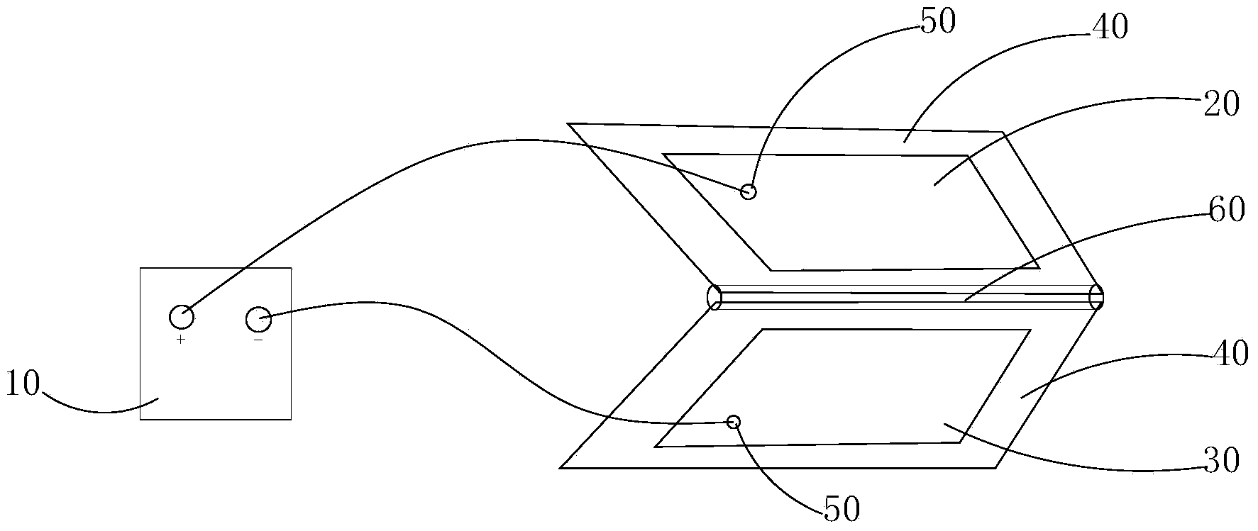
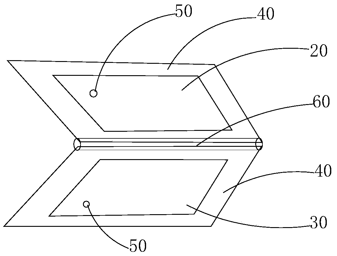
[0030] Such as figure 1 As shown, a test device for the short circuit risk between layers of a thin core board includes a withstand voltage tester 10, a first conductive plate 20, and a second conductive plate 30. A conductive plate 20 is electrically connected, and the negative electrode of the withstand voltage tester 10 is electrically connected to the second conductive plate 30 through a wire.

[0031] The two sides of the thin core plate are electrically contacted with the first conductive plate 20 and the second conductive plate 30 respectively, and positive voltage and negative voltage are respectively applied to the first conductive plate 20 and the second conductive plate 30, because the conductive plate and the thin core The board is in electrical contact, that is, a preset test voltage (such as 250V) is applied between the conductive patterns on both sides of the thin core board. It is sh...


PUM


Abstract

The invention discloses a test method, a test fixture and a test device for thin core board layer short risks. The test device comprises a dielectric strength tester, a first current-conducting board and a second current-conducting board, the anode of the dielectric strength tester is electrically connected with the first current-conducting board through a wire, and the cathode of the dielectric strength tester is electrically connected with the second current-conducting board through a wire. Since the first and second current-conducting boards contact with a thin core board electrically and respectively, if short defects are caused to any position on the thin core board relative to conductors at the moment or when the thickness of remaining dielectric is too small, the thin core board is broken down so as to be short. Therefore, whether the thin core board has short risks or not can be judged, if so, the thin core board is picked out to be scraped, rather than being misused continuously to cause scrap of an entire PCB (printed circuit board) during follow-up electronic testing. Evidently, by the test method, fixture and device, the thin core board with the short risks can be found out quickly in advance and is prevented from being misused to the follow-up lamination step, so that cost can be saved greatly, and working efficiency is improved greatly.

Description

technical field [0001] The invention relates to the technical field of circuit board testing, in particular to a method and a testing device for testing the short circuit risk between layers of a thin core board. Background technique [0002] With the continuous development of electronic products in the direction of multi-functionality, small size, light weight and high performance, the number of layers of printed circuit boards is getting higher and higher, and the dielectric thickness of the copper clad laminate core board used is also getting thinner (currently generally in Below 76um). Along with the thinning of medium thickness of thin core plate (the said thin core plate of the present invention refers to the core plate with etched pattern on both sides below 80um in thickness), if the size of debris in the medium or the length of the copper foil and copper teeth on both sides of the core plate If it is slightly larger, the insulation performance between the thin core...

Claims


Application Information

Patent Timeline
Patent Type & Authority Applications(China)
IPC IPC(8): G01R31/12G01R1/04
Inventor 李文杰王剑宫立军
Owner GUANGZHOU FASTPRINT CIRCUIT TECH
Why Eureka
Try Eureka