Detection system and detection method of battery capacity of super capacitor
A supercapacitor battery and detection system technology, which is applied in the direction of measuring electrical variables, measuring electricity, measuring devices, etc., can solve the problems of no clear standard for battery high-rate discharge capacity and charge acceptance, and restrict the development of new batteries, so as to reduce human intervention , The effect of improving test efficiency
- Summary
- Abstract
- Description
- Claims
- Application Information
AI Technical Summary
Problems solved by technology
Method used
Image

Examples
Embodiment Construction
[0021] In conjunction with accompanying drawing, the specific embodiment of the present invention is further described:
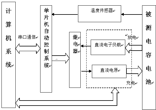
[0022] In one embodiment, a system for detecting the capacity of a supercapacitor battery includes: an electronic computer, a supercapacitor battery to be tested, a detection device, a relay, a temperature sensor, and a single-chip automatic control system. The electronic computer communicates with the single-chip microcomputer through the serial port. The electronic computer saves the test software for controlling the charging and discharging of the battery. The detection device transmits the test data of the DC electronic load and the DC power supply from the serial port to the computer through the software. The single-chip microcomputer controls the opening and closing of the relay to test the supercapacitor battery. The detection device includes a DC power supply for charging the battery, a DC electronic load for testing the battery capacity, and testin...
PUM
 Abstract
Description
Claims
Application Information
 - R&D
- Intellectual Property
- Life Sciences
- Materials
- Tech Scout
- Unparalleled Data Quality
- Higher Quality Content
- 60% Fewer Hallucinations
Browse by: Latest US Patents, China's latest patents, Technical Efficacy Thesaurus, Application Domain, Technology Topic, Popular Technical Reports.
© 2025 PatSnap. All rights reserved.Legal|Privacy policy|Modern Slavery Act Transparency Statement|Sitemap|About US| Contact US: help@patsnap.com