Automatic change-over switch with disengaging and engaging functions

An automatic transfer switch and function technology, applied in electrical switches, electrical components, circuits, etc., can solve the problems of difficult installation and debugging, low reliability, complex assembly, etc., to achieve convenient processing and manufacturing, improve assembly efficiency and reliability, and structure. Simple and reasonable design

Active Publication Date: 2014-12-24
ZHEJIANG CHINT ELECTRIC CO LTD
View PDF5 Cites 12 Cited by
  • Summary
  • Abstract
  • Description
  • Claims
  • Application Information

AI Technical Summary

Problems solved by technology

[0003] There are automatic transfer switches based on the principle of planetary gears that realize the clutch function in the transmission mechanism, such as a dual-power automatic transfer switch in the prior art, the clutch mechanism uses a positioning wheel, and the positioning wheel and the ring gear of the planetary gear set There is a gear meshing transmission relationship between them. Since the positioning wheel is driven by the ring gear of the planetary gear set to rotate during manual operation, the positioning wheel actually becomes a damping wheel, which is similar to the motor of the conventional transmission mechanism mentioned above. , it will also consume a lot of manual operation force, and because it is necessary to process all gears on the ring gear of the planetary gear set, and it is necessary to add a positioning wheel and a set of related shaft support mechanisms, there are many parts, complex assembly, and installation. Problems such as difficult debugging and low reliability

Method used


Image

  • Automatic change-over switch with disengaging and engaging functions
  • Automatic change-over switch with disengaging and engaging functions
  • Automatic change-over switch with disengaging and engaging functions

Examples


Embodiment Construction

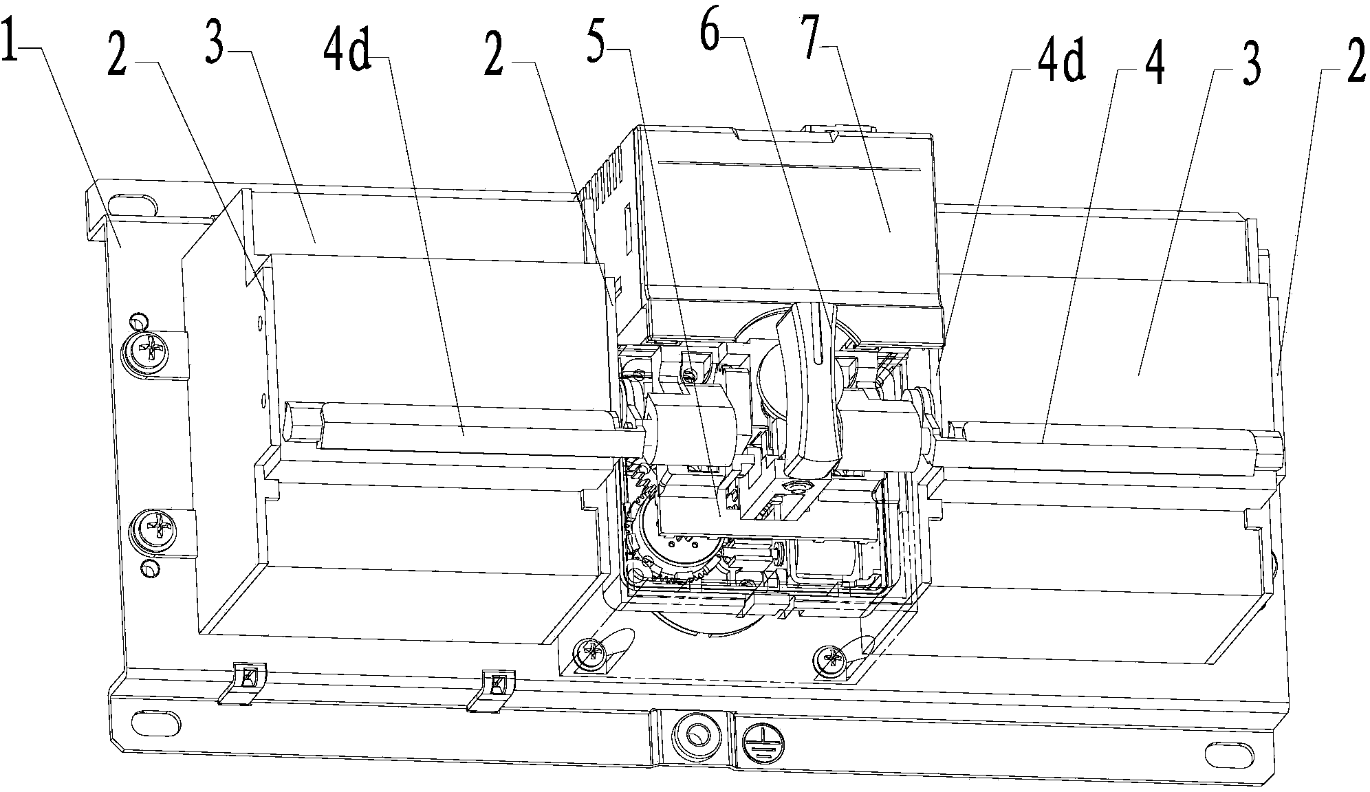
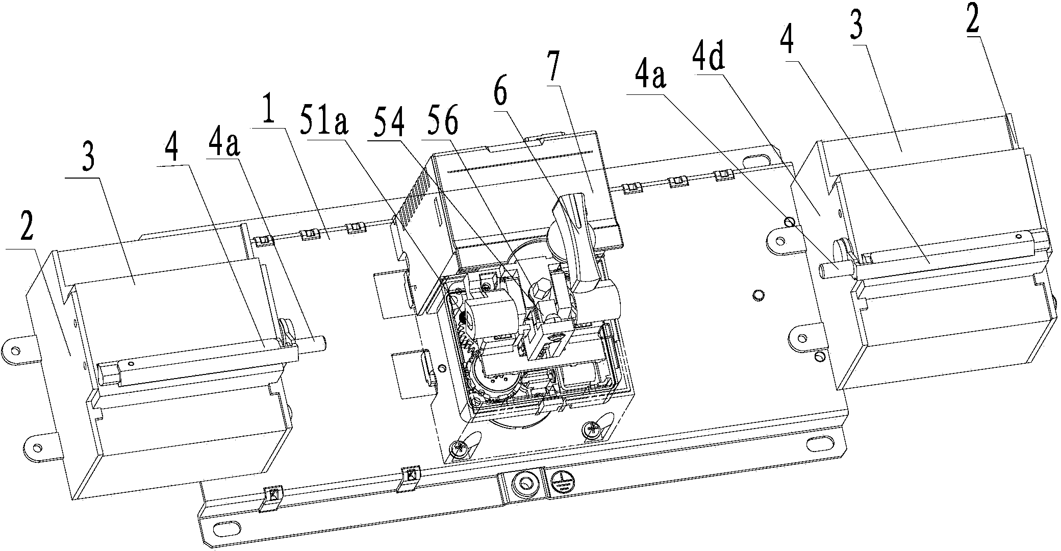
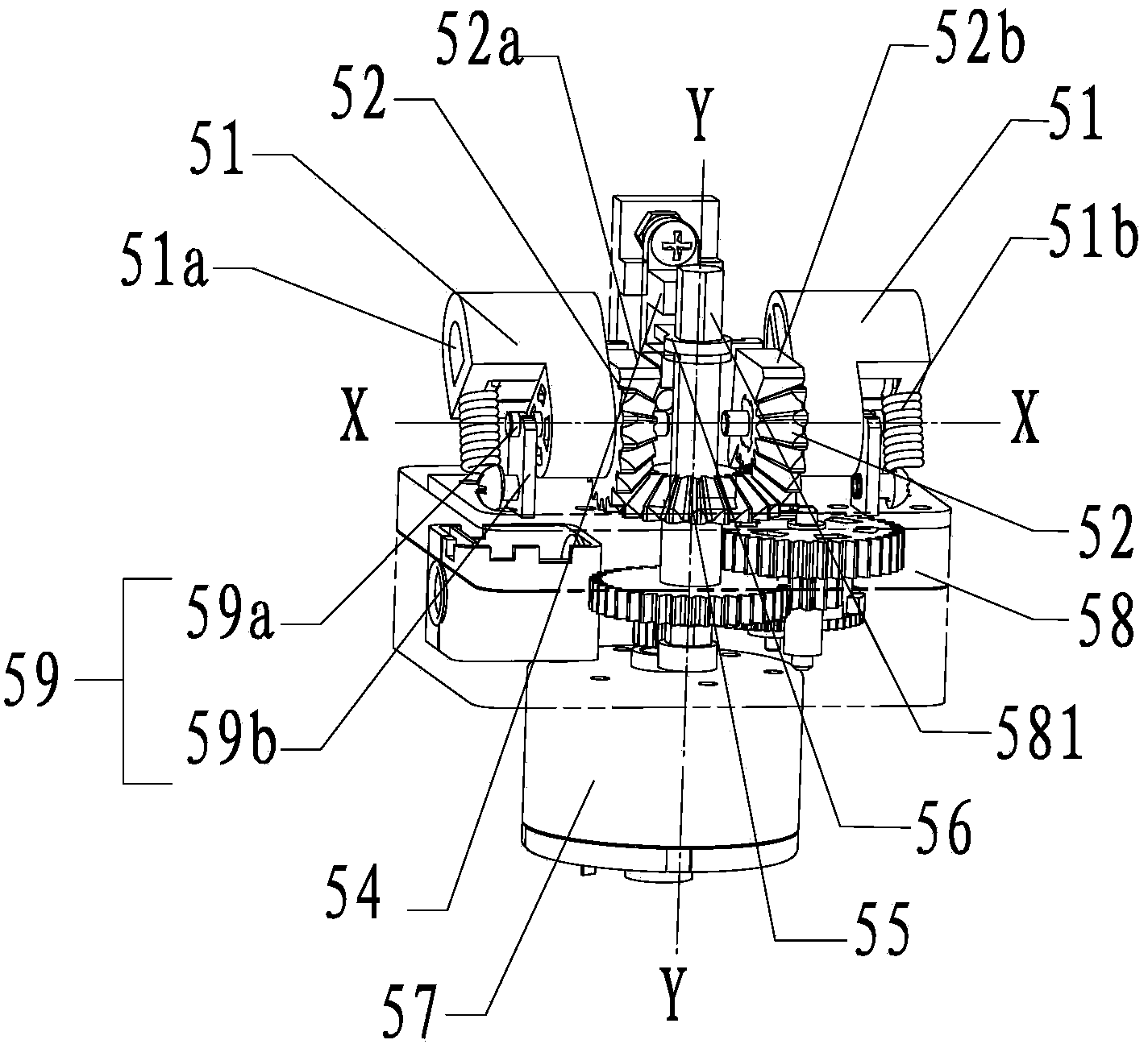
[0023] Combine below Figure 1 to Figure 8 The given examples further illustrate the specific implementation of the automatic transfer switch with clutch function of the present invention. The following descriptions of embodiments of the circuit breaker of the present invention are given as non-limiting examples only.

[0024] see figure 1 , figure 2 , the automatic transfer switch with clutch function of the present invention is a dual-power automatic transfer switch, comprising a base plate 1, two executive switches 3 fixed on the base plate 1, two operating handles respectively connected to each of the executive switches 3 Linked push rod 4, transmission mechanism 5, handle 6 of automatic transfer switch, controller 7, clutch mechanism and interlocking structure. Executing switch 3 can adopt circuit breaker to realize, and each executing switch 3 can pass through (but not limited to) such as figure 1 and figure 2The shown support structure is fixed on the base plate ...


PUM


Abstract

The invention provides an automatic change-over switch with disengaging and engaging functions. The automatic change-over switch with the disengaging and engaging functions comprises two actuation switches fixed to a bottom plate, two push rods, a transmission mechanism, a controller and an engaging and disengaging mechanism. The transmission mechanism comprises a motor, a reduction box, a horizontal bevel gear fixedly installed on an output shaft, two vertical bevel gears and two rocker arms, wherein the two vertical bevel gears are respectively in transmission with the horizontal bevel gear and are installed on the same horizontal axis through the corresponding horizontal shaft supporting mechanisms, and the two rocker arms are connected with the push rods through a link mechanism and are in linkage with the push rods. The reduction box comprises a planet gear set and a plurality of gear pairs. The engaging and disengaging mechanism is provided with a planet gear ring selective locking structure used for the planet gear set of the reduction box. The planet gear ring selective locking structure comprises an electromagnetic driving device, an ejector rod capable of moving in straight lines, and a boss arranged on the outer circle of each planet gear ring. The ejector rod interferes with the boss only when being electrically driven and enables the planet gear rings to be locked, the planet gear rings can rotate freely under manual operation, and disengaging and engaging of the transmission mechanism and the motor under the manual operation are achieved. The structure is simplified, and assembling efficiency and reliability are high.

Description

technical field [0001] The invention relates to the technical field of automatic transfer switches, in particular to a dual-power automatic transfer switch, in particular to a dual-power automatic transfer switch with a clutch function. Background technique [0002] With the rapid development of smart grid and uninterrupted power technology, the dual power supply system including main power supply and backup power supply is becoming more and more popular. One of the key technologies is to realize automatic switching and safe switching between main power supply and backup power supply. The dual power supply automatic transfer switch (hereinafter referred to as automatic transfer switch) is an electrical appliance that realizes this automatic switching and safe switching. At present, an automatic transfer switch is generally composed of two executive switches (circuit breakers) for on / off of the main power supply and the backup power supply, an electric and manual transmission...

Claims


Application Information

Patent Timeline
Patent Type & Authority Applications(China)
IPC IPC(8): H01H3/58H01H9/20
Inventor 黄甫
Owner ZHEJIANG CHINT ELECTRIC CO LTD
Why Eureka
Try Eureka