A solar cell busbar mask

A solar cell and mask technology, applied in circuits, photovoltaic power generation, electrical components, etc., can solve the problems of reducing solar cell conversion efficiency, unable to achieve mask effect, solar cell debris, etc. The effect of promoting and avoiding pollution

Inactive Publication Date: 2017-05-24
INST OF ELECTRICAL ENG CHINESE ACAD OF SCI +1
View PDF6 Cites 0 Cited by
  • Summary
  • Abstract
  • Description
  • Claims
  • Application Information

AI Technical Summary

Problems solved by technology

Although this improved screen mask can effectively reduce deformation and increase mask tension, the cost of laser burning or mechanical cutting is high, and the edges of the processed mask are rough and jagged, and the graphics The area near the edge becomes rough or has particles that are not easy to clean due to laser burning or instrument grinding, which not only fails to achieve a good masking effect, but also causes solar cell debris, which increases manufacturing costs
[0006] In addition, the screen mask also has the following disadvantages: (1) The thickness of the film layer prepared by the screen mask is too large, which will easily cause the film layer to absorb the incident light, inhibit the improvement of the conversion efficiency of the solar cell, and even reduce the Solar cell conversion efficiency
(2) The screen mask requires that the sediment to be deposited has a higher viscosity. If the sediment to be deposited is a solution prepared by water or an organic solvent (such as alcohol, isopropanol), since the solution has a strong fluidity, The deposited solution will flow towards the busbar area and flood the busbar, and the masking effect cannot be achieved

Method used


Image

  • A solar cell busbar mask
  • A solar cell busbar mask
  • A solar cell busbar mask

Examples


Embodiment Construction

[0036] The present invention will be further described below in conjunction with the accompanying drawings and specific embodiments.

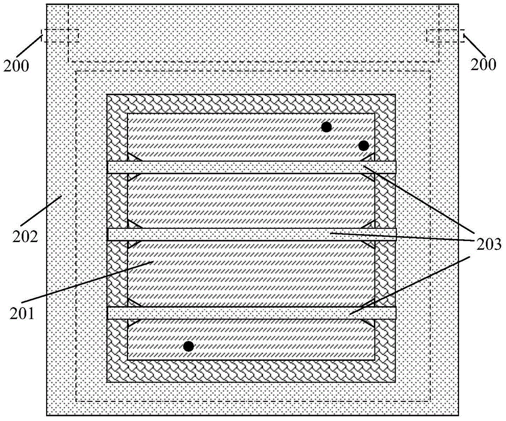
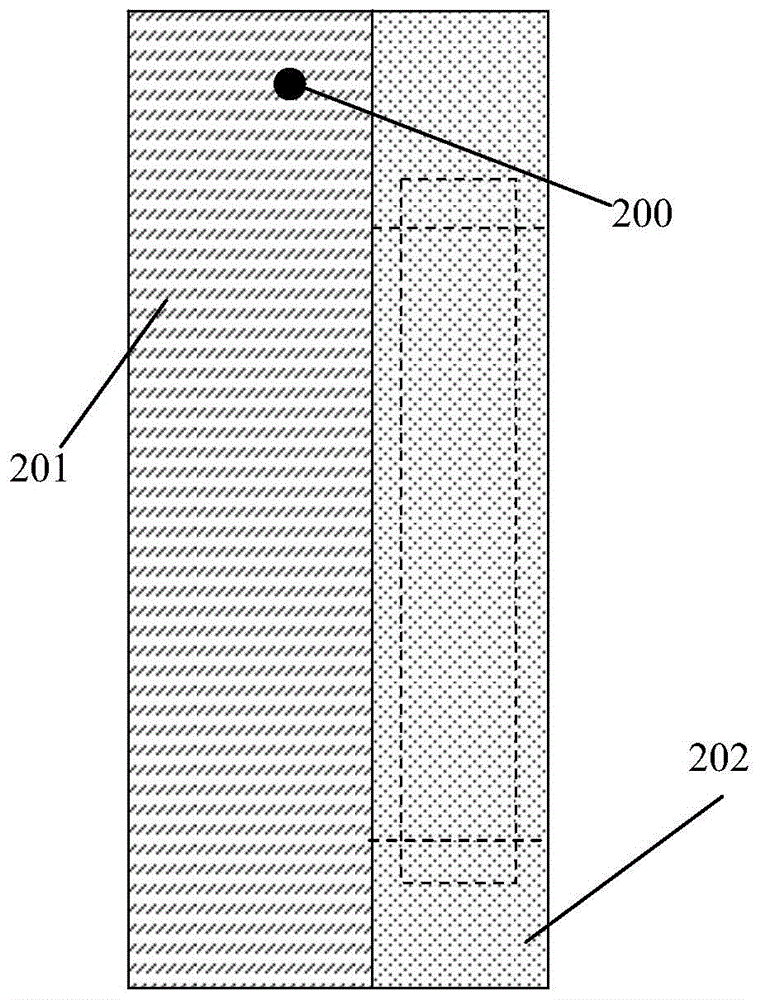
[0037] figure 2 , image 3 Shown is the solar cell busbar mask plate of the present invention. The busbar mask plate of the solar cell of the present invention is composed of an embolus 200 , a bottom plate 201 , a cover plate 202 and a mask strip 203 . The solar cell main grid mask plate is installed in a horizontal manner. The base plate 201 is arranged below, the cover plate 202 is placed on the base plate 201, and the plug 200 connects and fixes the base plate 201 and the cover plate 202 to form a loose-leaf hinge structure that can be opened and closed freely. The masking strips 203 are arranged in the middle area on the cover plate 202 , and the number of the masking strips 203 is the same as the number of busbars that need to be masked in the solar cell. figure 2 , image 3 The shown embodiment is used to realize the triple busbar...


PUM


Abstract

A solar battery main grid mask plate is composed of bolts (200), a base plate (201), a cover plate (202) and mask strips (203). The solar battery main grid mask plate is horizontally arranged. The base plate (201) is arranged at the lower portion. The cover plate (202) is arranged on the base plate (201). The mask strips (203) are arranged inside the middle area on the cover plate (202). The number of the mask strips (203) is equal to that of main grids needed when a solar battery forms a mask. Base plate latch holes and cover plate latch holes are symmetrically distributed in the sides of the base plate (201) and the cover plate (202) in the same direction. The bolts (200) are adopted for fixing the base plate and the cover plate through the base plate latch holes and the cover plate latch holes, so that the solar battery main grid mask plate forms a hinge structure capable of being opened and closed freely.

Description

technical field [0001] The invention relates to a device for preparing a solar cell, in particular to a main grid mask for realizing a mask for the main grid region. Background technique [0002] If a silicon oxide organic solution is deposited by spraying on the front surface of a conventional solar cell, and after annealing, it is decomposed to form a silicon oxide film, so that the front surface has a "silicon oxide / silicon nitride" double anti-reflection film structure, which can not only improve the conversion efficiency, Moreover, it is possible to prepare a solar cell with resistance to PID effect (potential induced degradation). However, this treatment method will cause the main grid of the solar cell to be covered by silicon oxide and cannot be welded, which will become an obstacle to the preparation of components. Therefore, a mask is required to avoid deposition of silicon oxide in the main gate region. [0003] At present, the ways to realize the busbar mask of...

Claims


Application Information

Patent Timeline
Patent Type & Authority Patents(China)
IPC IPC(8): H01L31/18
CPCH01L31/022425Y02E10/50Y02P70/50
Inventor 汤叶华周春兰王亚勋陈朋王磊王文静费建明王孟王俊英卢宝荣
Owner INST OF ELECTRICAL ENG CHINESE ACAD OF SCI
Why Eureka
Try Eureka