Dummy shaft for machining of doubly-fed wind generator collecting ring

A technology for wind power generators and collector rings, which is applied in the direction of collector maintenance, etc. It can solve the problems of collector ring surface burns, collector ring slideway burning, and cost increase, so as to ensure repair accuracy and quality, and make manufacturing convenient and practical , the effect of reducing labor intensity

Inactive Publication Date: 2014-12-24
襄阳中车电机技术有限公司
View PDF0 Cites 0 Cited by
  • Summary
  • Abstract
  • Description
  • Claims
  • Application Information

AI Technical Summary

Problems solved by technology

[0002] The rotor of the known doubly-fed wind generator is excited by a frequency converter. The main disadvantage of this type of wind generator is that the shaft voltage of the generator is too high, which leads to an increase in the bearing damage rate and an increase in runout, resulting in , There is a jump between the carbon brush and the slipway of the collector ring, the current of the ground wire of the collector ring increases, and the discharge between the slideway and the carbon brush results in burning of the slipway of the collector ring
On the other hand, the quality of the collector ring and the brush itself and technical problems such as brush assembly will also cause serious damage to the collector ring, which will inevitably cause serious failures
In the actual operation of the wind farm site, if the collector ring fails, 80% of it needs to be replaced, which leads to an increase in cost. At present, for the deflection of the collector ring with severe burns and serious wear, the commonly used manual fine sand grinding has been unable to solve

Method used


Image

  • Dummy shaft for machining of doubly-fed wind generator collecting ring
  • Dummy shaft for machining of doubly-fed wind generator collecting ring
  • Dummy shaft for machining of doubly-fed wind generator collecting ring

Examples


Embodiment Construction

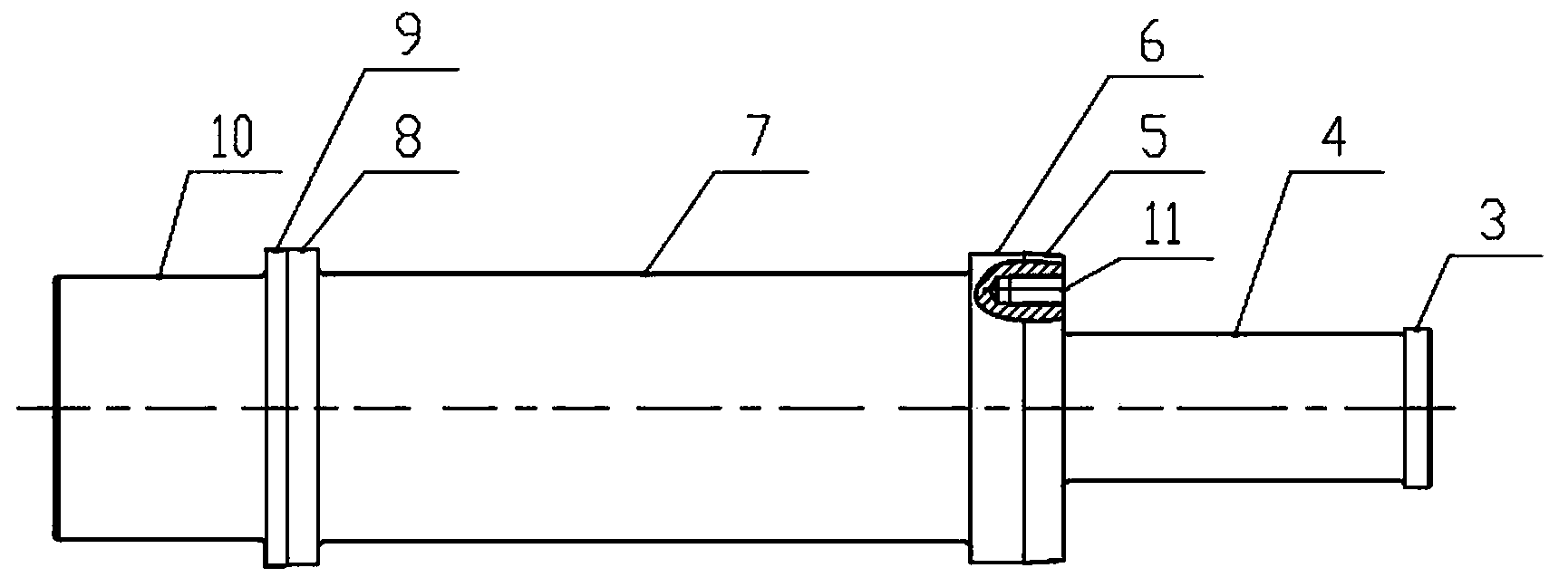
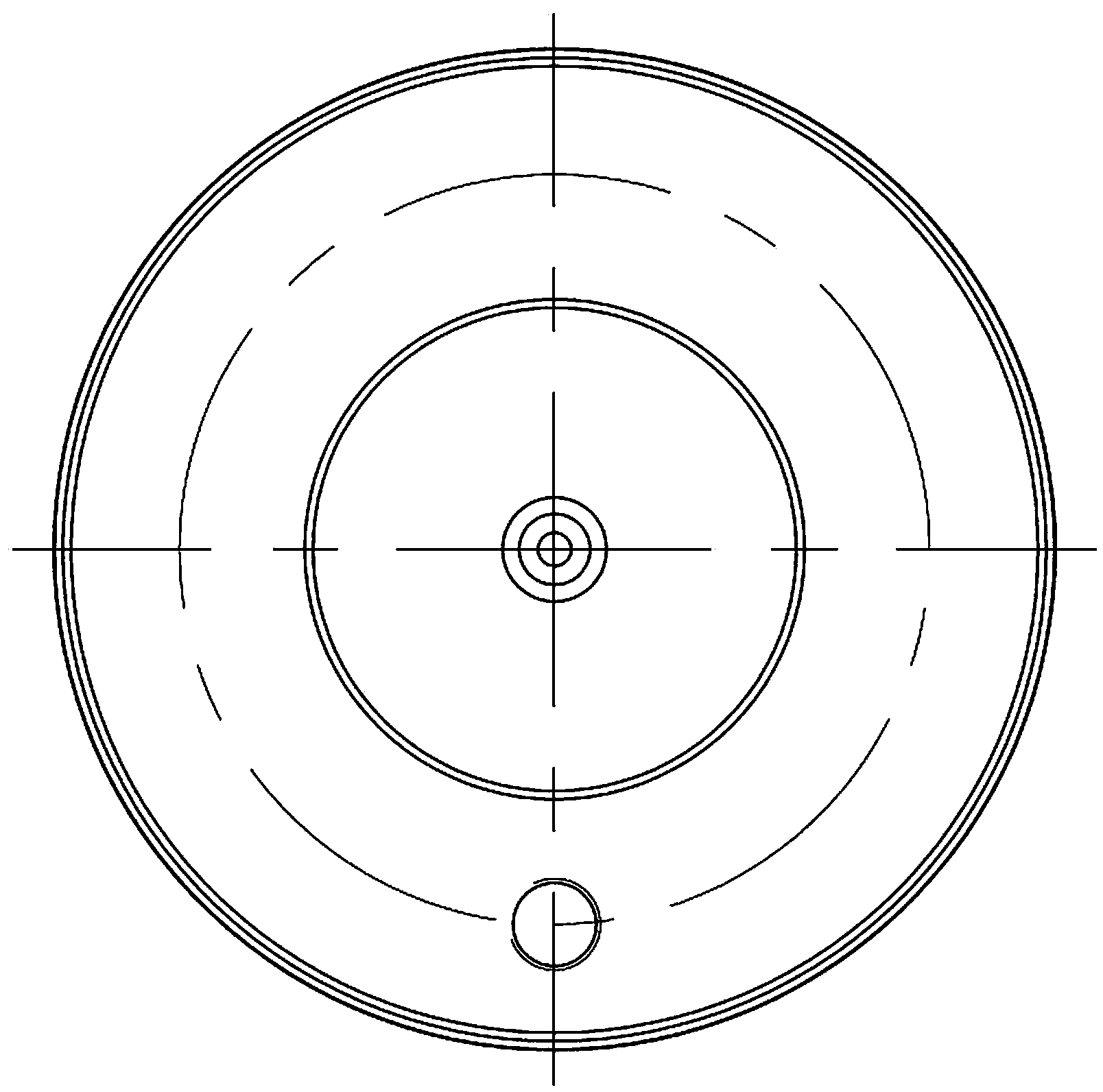
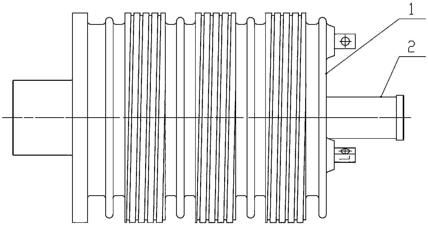
[0016] Such as figure 1 , 2 , 3, 4, and 5, the slip ring processing dummy shaft 2 consists of protruding shafts 8 and 6 respectively arranged on the two ends of the concave shaft 7 to form an I-shaped structure, and the two slip ring processing dummy shafts 2 The diameter of the protruding shafts 8, 6 matches the diameter of the inner hole of the collector ring 1, the axial distance between the two protruding shafts 8, 6 matches the axial length of the concave shaft 7 of the collector ring 1, when the collector When the electric ring processing dummy shaft 2 is installed in the inner hole of the collector ring 1, a small gap can be formed between the collector ring processing dummy shaft 2 and the inner hole of the collector ring 1, and the collector ring processing dummy shaft 2 has an I-shaped The type structure can reduce the contact area between the collector ring 1 and the collector ring processing dummy shaft 2, so as to reduce the resistance; the outer side of the prot...


PUM


Abstract

The invention discloses a dummy shaft for machining of a wind generator collecting ring and relates to a dummy shaft for fine machining of the surface of a doubly-fed wind generator collecting ring. The dummy shaft mainly solves the problem that cost is high due to the fact that the collecting ring needs to be replaced when the surface of the collecting ring is abraded severely or obvious burn marks and sink marks are formed in the surface of the collecting ring. According to the dummy shaft, an H-shaped structure is formed by a concave shaft and convex shafts arranged at the two ends of the concave shafts respectively, a tensioning cone and a technology jerk value step are sequentially arranged on the outer side of one convex shaft, a guiding cone and a technology jerk value step are sequentially arranged on the outer side of the other convex shaft, and a threaded hole is formed in the circumference of the guiding cone in the axial direction. By the adoption of the dummy shaft, it can be guaranteed that the jerk values of the surface of the collecting ring before and after machining meet requirements, and the whole dummy shaft for machining of the collecting ring is H-shaped, so that the contact area between the dummy shaft and the interior of the collecting ring is reduced and friction resistance is reduced; labor intensity is low and efficiency is high.

Description

technical field [0001] The invention relates to the processing of collector rings of wind power generators, in particular to a device for repairing the working surface of collector rings of double-fed wind power generators. Background technique [0002] The rotor of the known doubly-fed wind generator is excited by the frequency converter. The main disadvantage of this type of wind generator is that the shaft voltage of the generator is too high, which leads to an increase in the damage rate of the bearing and an increase in the runout, which causes the generator to rotate. , There is a jump between the carbon brush and the slipway of the collector ring, the current of the ground wire of the collector ring increases, and the discharge between the slideway and the carbon brush results in burning of the slipway of the collector ring. On the other hand, the quality of the collector ring and the brush itself and technical problems such as brush assembly will also cause serious d...

Claims


Application Information

Patent Timeline
Patent Type & Authority Applications(China)
IPC IPC(8): H01R43/14
Inventor 马暖
Owner 襄阳中车电机技术有限公司
Why Eureka
Try Eureka