Photovoltaic power generation system employing virtual grounding technology

A photovoltaic power generation system and virtual grounding technology, applied in photovoltaic power generation, photovoltaic modules, electrical components, etc., can solve problems such as performance degradation

Active Publication Date: 2014-12-24
SHANGHAI CHINT POWER SYST +1
View PDF3 Cites 17 Cited by
  • Summary
  • Abstract
  • Description
  • Claims
  • Application Information

AI Technical Summary

Problems solved by technology

[0008] The purpose of the present invention is to provide a simple, low-cost photovoltaic power generation system solution, and can solve the problem of performance degradation of components caused by potential induced attenuation

Method used


Image

  • Photovoltaic power generation system employing virtual grounding technology
  • Photovoltaic power generation system employing virtual grounding technology
  • Photovoltaic power generation system employing virtual grounding technology

Examples


Embodiment 1

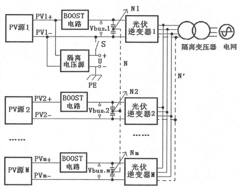
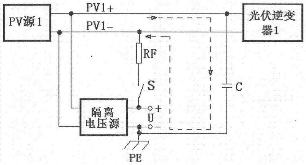
[0029] Aiming at a photovoltaic power generation system with multiple parallel photovoltaic inverters, the present invention provides a solution to the potential-induced attenuation of solar panels. The photovoltaic inverter system includes: a photovoltaic battery module, a photovoltaic inverter, an isolation transformer and an isolation DC voltage source. The direct current output by the photovoltaic cell module is converted into alternating current by the photovoltaic inverter, and then fed back to the grid through the isolation transformer. Add an isolated DC voltage source between the input negative pole of one of the photovoltaic inverters and the ground, so as to increase the voltage of the negative pole of the photovoltaic inverter system to the ground, so that the voltage of the negative pole of the photovoltaic inverter system to the ground is positive , to achieve the purpose of reducing the PID effect of photovoltaic modules.

[0030] refer to figure 1 , M photovo...

Embodiment 2

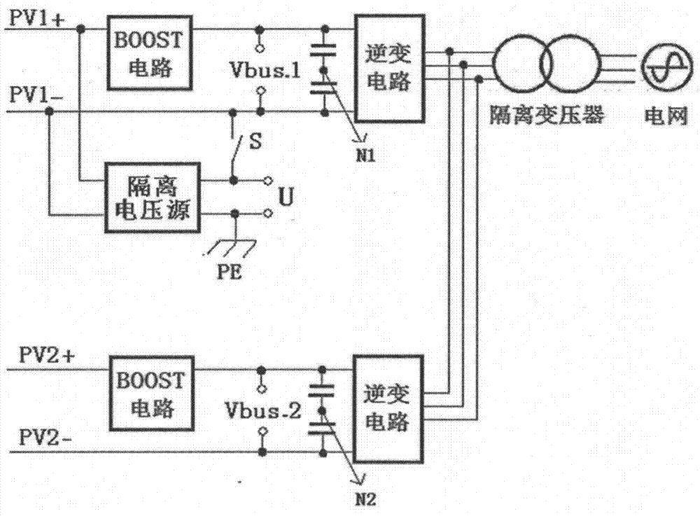
[0047] refer to Figure 9 , the solution provided by the present invention can also be used to connect the positive electrode of the photovoltaic inverter to the isolated voltage source. Due to the difference in the materials of the solar panels, the photovoltaic power generation system using some solar panels needs to prevent the degradation of the performance of the photovoltaic modules caused by the PID effect. The potential of the solar module to the ground is negative, that is, the positive potential of the photovoltaic inverter is required to be less than zero to the ground. When the positive pole of the photovoltaic system is connected to the isolated voltage source, the positive pole of the isolated voltage source is connected to the ground, and the negative pole is connected to the photovoltaic system through a controllable switch. The positive pole of the inverter, so that during the daytime, the photovoltaic power generation system is normally connected to the grid a...


PUM


Abstract

The invention relates to a photovoltaic power generation system employing a virtual grounding technology. The system comprises M photovoltaic inverters which are parallelly connected to generate power. The output ends of all photovoltaic inverters are connected with the input end of a same isolation transformer; the input end of each photovoltaic inverter is connected with at least one solar panel. The system is characterized in that an isolation direct-current voltage source used for increasing voltage applied to the ground by a cathode of the current photovoltaic inverter is connected between a cathode of only one photovoltaic inverter and the ground, among the M photovoltaic inverters; or an isolation direct-current voltage source used for decreasing the voltage applied to the ground by an anode of the current photovoltaic inverter is connected between the anode of only one photovoltaic inverter and the ground, among the M photovoltaic inverters. A solution to Potential induced attenuation of solar panels is provided for the photovoltaic power generation system with the multiple parallel photovoltaic inverters, the problem that unit performance decrease caused by PID (plasma-induced charging damage) effect can be effectively prevented, and the system is simple, feasible and low in cost.

Description

technical field [0001] The invention relates to a photovoltaic power generation system capable of solving potential-induced attenuation, and belongs to the technical field of new energy grid-connected power generation. Background technique [0002] As an important part of new energy, solar power has been developing more and more. However, as the scale of the photovoltaic industry continues to expand, there are differences and uncertainties in the use environment, especially in some areas with relatively harsh environmental conditions. With the extension of time, there have been a series of problems in which the power generation of power stations has decreased and the power of photovoltaic modules has decreased. As one of the main reasons for the power drop of photovoltaic modules, the PID phenomenon has attracted extensive attention. [0003] Potential Induced Degradation (PID, Potential Induced Degradation) of photovoltaic modules refers to: when a solar module and the gr...

Claims


Application Information

Patent Timeline
Patent Type & Authority Applications(China)
IPC IPC(8): H02J3/38H02S40/30
CPCY02E10/56
Inventor 张玉林朱国忠杨敏杨野张俊
Owner SHANGHAI CHINT POWER SYST
Why Eureka
Try Eureka