Method for matching digital video signal transmission format of infrared thermal imaging machine core

An infrared thermal imaging and digital video technology, applied in the field of image transmission, can solve the problems of difficulty in secondary development and poor versatility, and achieve the effects of fast computing speed, strong versatility and simple interface

Active Publication Date: 2014-12-24
JING LIN CHENGDU SCI & TECH
View PDF6 Cites 6 Cited by
  • Summary
  • Abstract
  • Description
  • Claims
  • Application Information

AI Technical Summary

Problems solved by technology

[0005] In order to overcome the technical defects of fixed transmission interface, poor versatility and difficulty in secondary development in the existing infrared thermal imaging video signal transmission process, the present invention discloses a digital video signal transmission format matching method for infrared thermal imaging core

Method used


Image

  • Method for matching digital video signal transmission format of infrared thermal imaging machine core
  • Method for matching digital video signal transmission format of infrared thermal imaging machine core
  • Method for matching digital video signal transmission format of infrared thermal imaging machine core

Examples


Embodiment 1

[0039] Embodiment 1: Taking a 16-bit interface bus as an example, one pixel outputs RGB666 format in two clock cycles. The final color image output data format requirements are as follows:

[0040]

[0041] Proceed as follows:

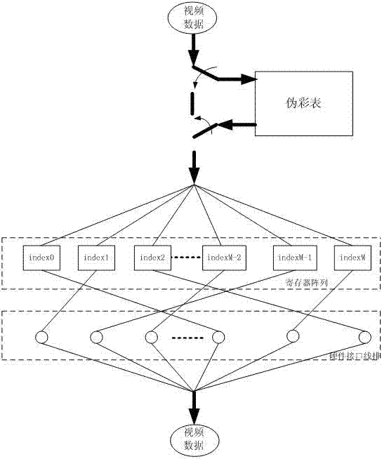
[0042] 1. Configure the pseudo color table,

[0043] For the color data format, since the data output by the infrared sensor is a grayscale format with only black and white colors, the subsequent output data uses grayscale to define the color, and the grayscale data needs to be converted into data in a color format. In this embodiment, the output RGB666, the data conversion table of this embodiment is actually a pseudo-color table, quantized into the following format, the present embodiment uses 8-bit original grayscale format, and the format after pseudo-color conversion is RGB888.

[0044]

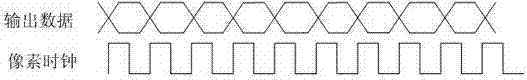
[0045] 2. Configure the pixel clock cycle register as 2 clock cycles per pixel

[0046] 3. Configure the output hardware interface line mapping table

...

Embodiment 2

[0054] Embodiment 2: Taking an 8-bit interface bus, one pixel outputs the YCbCr444 format in three clock cycles as an example.

[0055] The format requirements are as follows:

[0056]

[0057] Proceed as follows:

[0058] 1. Configure the pseudo color table, because the output is in YCbCr format, the format is as follows

[0059]

[0060] 2. Configure the pixel clock period register as 3 clock periods per pixel;

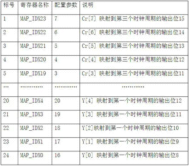
[0061] 3. Configure the interface bus mapping table

[0062] The mapping table is set as 32 5-bit registers in this example, marked as:

[0063] MAP_IDXi (i = 0,1,2...31), the subscript i is the value of the register;

[0064] Register values ​​0~23 respectively correspond to the data bits after pseudo-color transformation in 1. Register values ​​24~27 are mapped to data 0, register values ​​28~31 are mapped to data 1,

[0065] Among them, MAP_IDX0~MAP_IDX7 correspond to the first clock cycle;

[0066] Among them, MAP_IDX8~MAP_IDX15 correspond to the seco...


PUM


Abstract

The invention provides a method for matching a digital video signal transmission format of an infrared thermal imaging machine core. The method comprises a data conversion step and a data output step; the data conversion step comprises S1, forming a data conversion table according to the format configurations of the input gray scale data and display data to be output, S2, configuring the output clock period number and the output time sequence of individual pixels to form a pixel time sequence table, and S3 configuring and outputting a hardware interface line mapping table; the data output step comprises S4, converting the input gray scale data into display data according to the data conversion table in the step S1, S5, reconfiguring the display data obtained in the step S4 to each data line of a hardware interface according to the hardware interface line mapping table in the step S4, and S6, performing different-time outputting according to the pixel time sequence table in the step S2. The method for matching the digital video signal transmission format of the infrared thermal imaging machine core has the advantages of no any extra hardware increased, real-time data updating according to software setting, high operation speed, available expansion of desired formats according to application requirements, and high universality.

Description

technical field [0001] The invention belongs to the field of image transmission, and relates to a method for transmitting infrared thermal imaging data, in particular to a method for matching transmission formats of digital video signals of an infrared thermal imaging core. Background technique [0002] A typical infrared thermal imaging core consists of a front-end infrared lens, an infrared image sensor and a front-end infrared image processing circuit. The infrared radiation of the object is collected by the infrared lens and projected to the infrared image sensor. The infrared sensor completes the photoelectric conversion, and converts it into an electrical signal through the analog-to-digital conversion circuit. Video interface output. The back-end image application processor receives the video signal from the infrared core, and completes the functions of transmission, display and storage according to the application requirements after internal image post-processing. ...

Claims


Application Information

Patent Timeline
IPC IPC(8): H04N7/01H04N5/765
CPCH04N5/765
Inventor 曾衡东吴海宁殷刚
Owner JING LIN CHENGDU SCI & TECH
Why Eureka
Try Eureka