
Method and mobile device for reducing the thermal resistance between two solids

A technology of heat transfer element and initial position, which is applied in the field of storage brackets, can solve the problems of affecting the dischargeable power, contact may only occur on one generator or simply several areas, etc., so as to save machining costs and reduce Space, the effect of optimizing the number of transports

Inactive Publication Date: 2014-12-24
COMMISSARIAT A LENERGIE ATOMIQUE ET AUX ENERGIES ALTERNATIVES
View PDF7 Cites 0 Cited by
  • Summary
  • Abstract
  • Description
  • Claims
  • Application Information

AI Technical Summary

Problems solved by technology

If both gaps are eliminated the power becomes 8.75 (i.e. +40% increase), however, in this technique the surfaces positioned to contact are important (approximately 1 / 4 of the outer surface of the bracket), Thus unless there are overall acceptable manufacturing tolerances, contact may only occur on one generator or simply on several areas
[0031] Therefore, the gaps inside storage or transport tanks (where the thickness of the gaps creates an important thermal contact resistance) and thermal standards must not be exceeded, which greatly affects the dischargeable power during the transport of fuel assemblies

Method used


Image

  • Method and mobile device for reducing the thermal resistance between two solids
  • Method and mobile device for reducing the thermal resistance between two solids
  • Method and mobile device for reducing the thermal resistance between two solids

Examples


Embodiment Construction

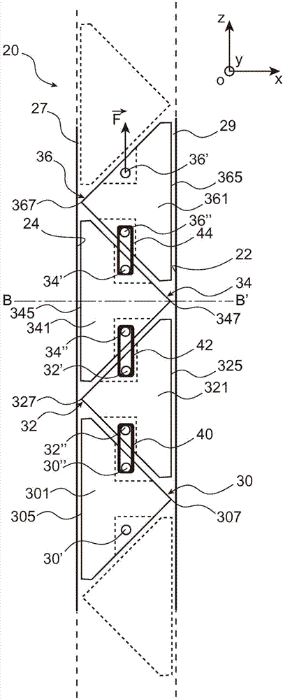
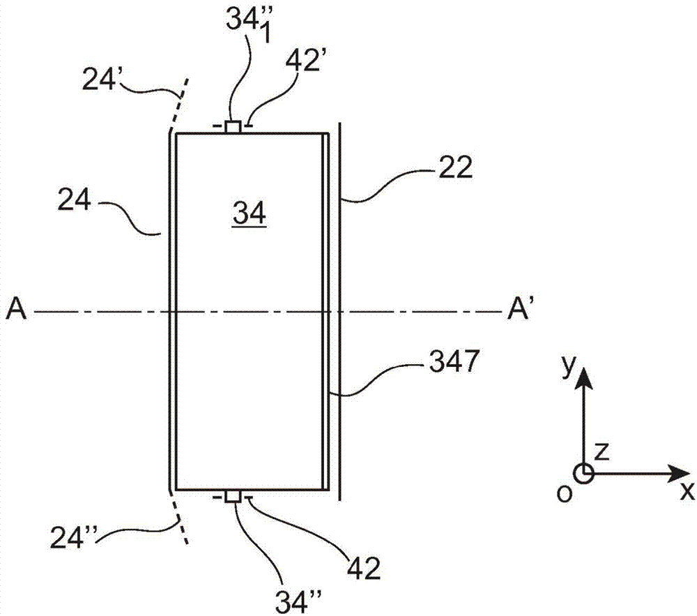
[0079] First refer to Figure 2A (along Figure 2B sectional side view of the plane AA' or xOz cut) and Figure 2B (along Figure 2A Plane BB' or xOy cut section top view), Figure 2A and Figure 2B A stack of heat transfer elements 30, 32, 34, 36 of a bracket system 20 according to a particular embodiment of the invention is shown.

[0080] exist Figure 2A In , it can be seen that a plurality of heat transfer elements are stacked along the direction Oz of the trièdre trirectangle Oxyz. exist Figure 2A in and in Figure 2B Also shown in are two walls 22, 24 which are respectively the hot and cold walls of the environment in which the stack is located (the wall 22, called the hot wall, is located in the panier). The thermal component side of the interior; and the wall 24, called the cold wall, is on the immediate ambient side of the outside of the carrier). Outside the aforementioned environment, reference numerals 22 and 24 are two planes delimiting the transverse e...


PUM


Abstract

The invention relates to a substantially prismatic transmitter element (30, 32, 34, 36) for a nuclear fuel storage rack, comprising three main surfaces (303, 303', 305, 325, 345, 365), including a base and two secondary planar surfaces, and two side surfaces (301, 301') made of a heat-transmitting material, and which are provided, on the sides thereof, with a means for pulling the element in a direction parallel to the base.

Description

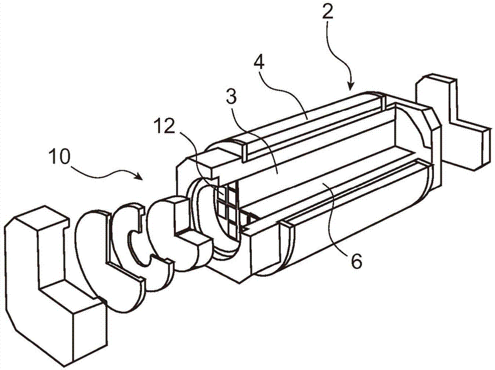
technical field [0001] The invention relates to a storage rack for nuclear fuel assemblies consisting of a plurality of adjacent units of great length into which a fuel assembly or optionally several rods of a fuel assembly can be introduced. in each unit in the unit. Background technique [0002] The storage pallets (also referred to as storage baskets) are intended for storing and / or transporting fuel assemblies, optionally encapsulated or shielded or not encapsulated or shielded. The storage racks are suitable for irradiated fuel, but can also be used for fresh fuel. The storage tray may be used in dry or wet media, for example during storage of fuel in a pool or during introduction of fuel into a transport or storage enclosure. [0003] The solution provided for the needs of the different functions (radiation protection, impact resistance, fire resistance, etc.) of tanks for transporting fuel assemblies is stacks of different materials. The restriction on the internal...

Claims


Application Information

Patent Timeline
IPC IPC(8): G21F5/012G21F5/10
CPCG21F5/012G21F5/10
Inventor 让克洛德·博纳尔伯纳德·迪雷
Owner COMMISSARIAT A LENERGIE ATOMIQUE ET AUX ENERGIES ALTERNATIVES
Learn More