Supercharge Your Innovation With Domain-Expert AI Agents!

Lubricating structure for linear compressor

A technology of linear compressors and lubricating structures, which is applied in mechanical equipment, machines/engines, liquid displacement machinery, etc. It can solve the problems of linear compressor performance degradation and high temperature, so as to suppress temperature rise, performance improvement, Avoid the effects of dry friction

Active Publication Date: 2014-12-31
QINGDAO HAIER SMART TECH R & D CO LTD
View PDF6 Cites 3 Cited by
  • Summary
  • Abstract
  • Description
  • Claims
  • Application Information

AI Technical Summary

Problems solved by technology

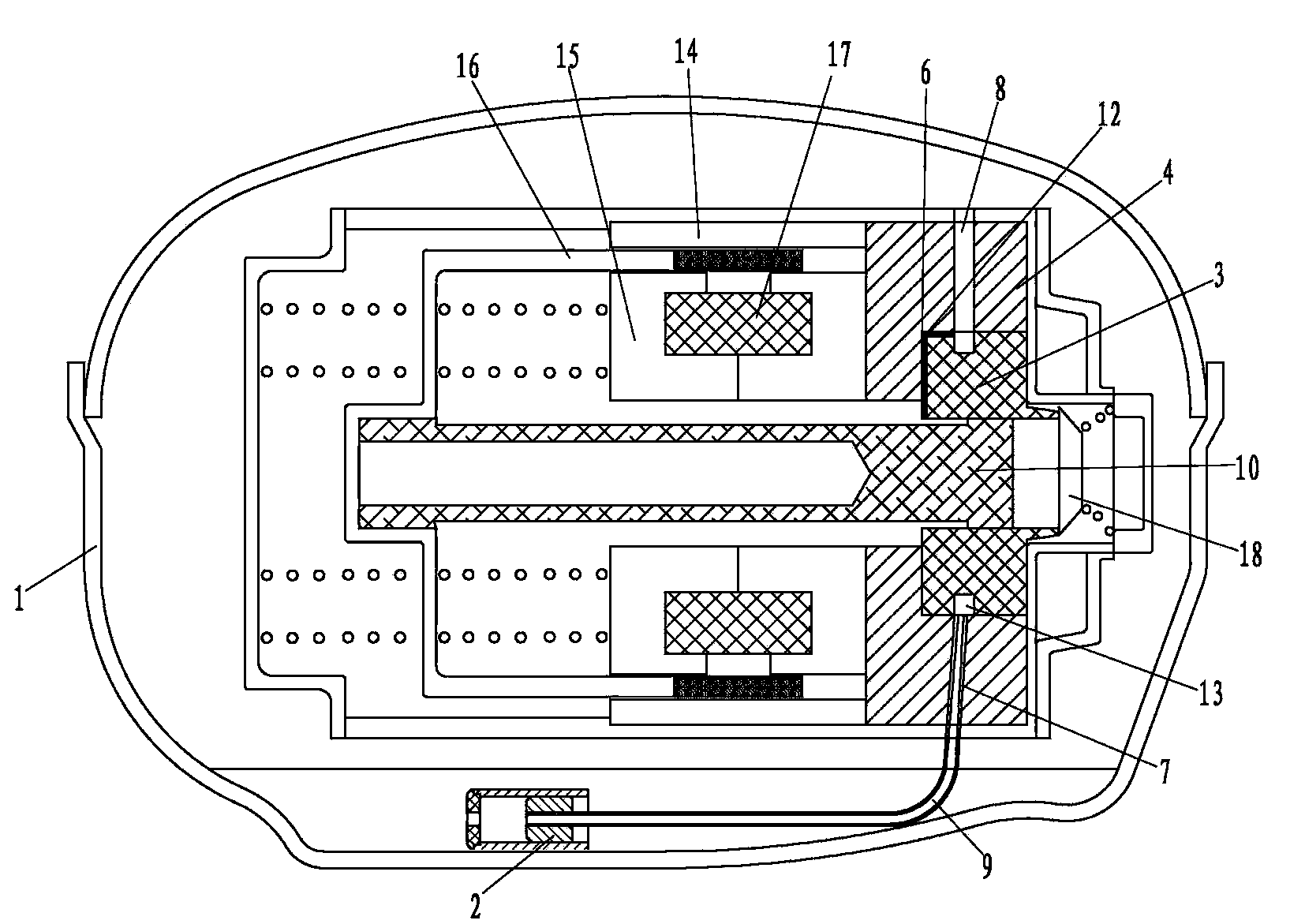
Under the action of the magnetic field force, the mover reciprocates in the axial direction, and the mover drives the piston to reciprocate along the inner cavity of the cylinder, thereby compressing the refrigerant gas filled in the compression chamber. After the refrigerant gas is compressed, a large amount of heat is released. At the same time, the friction between the outer surface of the piston and the inner wall of the cylinder increases the temperature of the contact part between the piston and the cylinder, and the heat increases the temperature of the cylinder, which easily leads to a decrease in the performance of the linear compressor.

Method used


Image

  • Lubricating structure for linear compressor
  • Lubricating structure for linear compressor
  • Lubricating structure for linear compressor

Examples


Embodiment Construction

[0015] The present invention will be further described below in conjunction with the accompanying drawings and specific embodiments, so that those skilled in the art can better understand the present invention and implement it, but the examples given are not intended to limit the present invention.

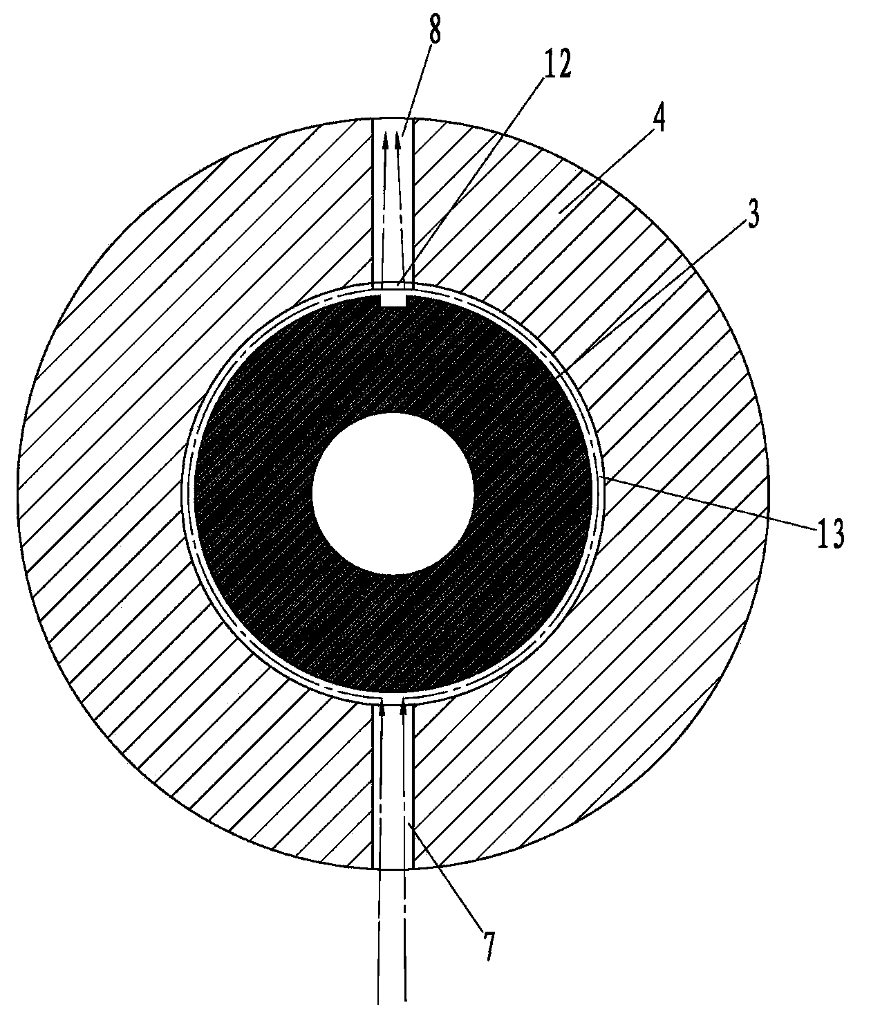
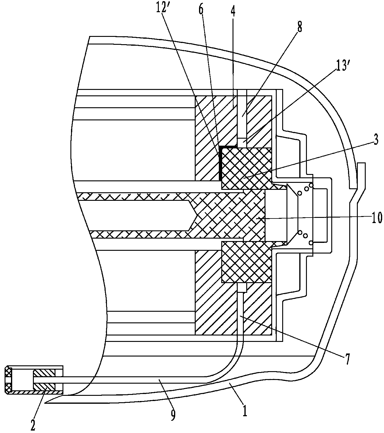
[0016] Such as figure 1 and figure 2 As shown, it is a structural schematic diagram of the first embodiment of the lubricating structure of the linear compressor of the present invention, including the shell 1, and lubricating oil is stored at the bottom of the inner cavity of the shell 1. The shell 1 is equipped with a cylindrical outer stator 14, the inner cavity of the outer stator 14 is provided with a cylindrical inner stator 15, the outer stator 14 and the inner stator 15 are coaxial, and a circle is inserted between the outer stator 14 and the inner stator 15. Cylindrical mover 16. The inner stator 15 has a built-in coil 17, and a coaxial piston 10 is arranged in the inn...


PUM


Abstract

The invention discloses a lubricating structure for a linear compressor. The lubricating structure for the linear compressor comprises an air cylinder and a front flange; an oil supply pipeline is arranged on the front flange; a first oil pipeline which can transport lubricating oil from the oil supply pipeline to the piston surface is arranged between the front flange and a combination surface of the air cylinder. The lubricating structure for the linear compressor can reduce friction between a piston and the air cylinder wall and restrain temperature of a contact position of the piston and the air cylinder wall from rising and enables the linear compressor performance to be improved.

Description

technical field [0001] The invention relates to a linear compressor, in particular to a lubricating structure of a linear compressor. Background technique [0002] The existing linear compressor includes a shell, and lubricating oil is stored at the bottom of the inner cavity of the shell. The shell is equipped with a cylindrical outer stator, the inner cavity of the outer stator is provided with a cylindrical inner stator, the outer stator and the inner stator are coaxial, and a cylindrical mover is inserted between the outer stator and the inner stator. The inner stator has a built-in coil, and a coaxial piston is set in the inner cavity of the inner stator. One end of the piston is movably inserted on the mover, and the other end is movably inserted in the inner cavity of the cylinder, and an exhaust valve is installed in the cylinder. Piston, cylinder and exhaust valve together form a compression chamber with built-in refrigerant gas. When the coil is energized, the in...

Claims


Application Information

Patent Timeline
IPC IPC(8): F04B39/02
Inventor 宋斌李衡国闫赛娜赵志强许升李标
Owner QINGDAO HAIER SMART TECH R & D CO LTD
Features
  • R&D
  • Intellectual Property
  • Life Sciences
  • Materials
  • Tech Scout
  • Unparalleled Data Quality
  • Higher Quality Content
  • 60% Fewer Hallucinations
Learn More