Eureka AIR delivers breakthrough ideas for toughest innovation challenges, trusted by R&D personnel around the world.

Imaging device and method for manufacturing same

A camera device, pixel technology, applied in radiation control devices, diodes, semiconductor devices, etc., can solve problems such as color mixing and crosstalk

Inactive Publication Date: 2014-12-31
KK TOSHIBA
View PDF6 Cites 0 Cited by
  • Summary
  • Abstract
  • Description
  • Claims
  • Application Information

AI Technical Summary

Problems solved by technology

However, in back-illuminated devices, color mixing (crosstalk) between adjacent pixels is prone to occur

Method used


Image

  • Imaging device and method for manufacturing same
  • Imaging device and method for manufacturing same
  • Imaging device and method for manufacturing same

Examples


Embodiment Construction

[0015] Embodiments are described below with reference to the drawings. In the drawings, the same reference numerals are given to the same parts, and detailed descriptions are appropriately omitted, and different parts will be described. In addition, the drawings are shown schematically or conceptually, and the relationship between the thickness and width of each part, the ratio of the sizes between parts, and the like are not necessarily the same as the real ones. In addition, even when the same parts are shown, mutual dimensions or ratios may differ depending on the drawings.

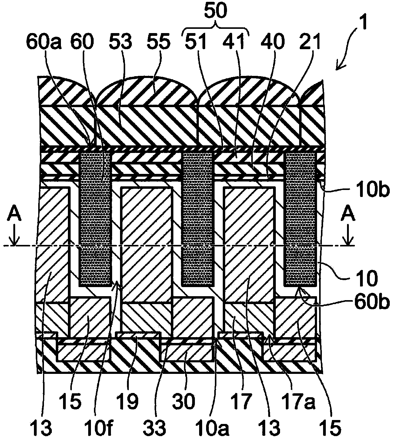
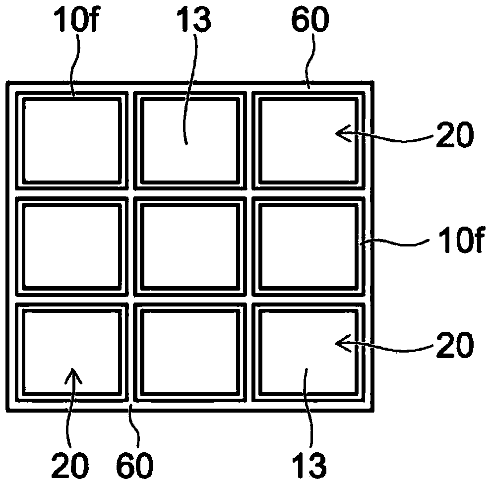
[0016] FIG. 1 is a schematic diagram showing an imaging device 1 according to an embodiment. FIG. 1( a ) shows a partial cross section of the imaging device 1 . Fig. 1(b) shows a cross section along line A-A shown in Fig. 1(a).

[0017] The imaging device 1 includes a semiconductor layer 10 , a plurality of pixels 20 provided on the semiconductor layer 10 , and an electrode 30 for controlling the ou...


PUM


Abstract

According to one embodiment, an imaging device includes a semiconductor layer, an electrode, first and second insulating films, and a light blocking film. The semiconductor layer has a first surface and a second surface on an opposite side to the first surface, and includes pixels configured to detect light. The electrode is provided on the first surface and is configured to control an output of the pixels. The light blocking film defines the boundaries of the pixels. The first insulating film is provided on the second surface. The second insulating film is provided on the upper surface of the first insulating film and has a smaller refractive index in a visible light range than the first insulating film. One end of the light blocking film is located in the second insulating film or at a same level as a surface of the second insulating film. Another end of the light blocking film is located in the semiconductor layer.

Description

[0001] (Citation of relevant literature) [0002] This application is based on and claims priority from Japanese Patent Application No. 2013-134280 filed on June 26, 2013, the entire content of which is hereby incorporated by reference. technical field [0003] The present invention relates to an imaging device and a manufacturing method thereof. Background technique [0004] An imaging device such as a CCD (Charge Coupled Device) or a CMOS image sensor (Complimentary Metal Oxide Semiconductor image sensor) includes a plurality of pixels that perform photoelectric conversion, and a circuit unit that outputs an image signal that combines the outputs of the individual pixels. There are two types of imaging devices, one is a surface-illuminated device in which both pixels and circuit parts are provided on one chip surface, and the other is a back-illuminated device in which a circuit part is provided on the front side and pixels are provided on the back side. Among them, the b...

Claims


Application Information

Patent Timeline
IPC IPC(8): H01L27/146
CPCH01L27/14621H01L27/14623H01L27/14627H01L27/1463H01L27/1464H01L27/14643H01L27/14689H01L31/0232H01L31/18
Inventor 福水裕之南孝明江田健太郎用正武
Owner KK TOSHIBA
Why Eureka
Eureka Blog
Learn More