Infrared automatic hand drier circuit

An infrared and hand dryer technology, applied in the circuit field, can solve paper waste and other problems, and achieve the effects of low production cost, simple structure and fast response speed

Active Publication Date: 2015-01-07
TONGXIANG HUIFENG ELECTRICAL APPLIANCE DIE CASTING PLANT
View PDF9 Cites 3 Cited by
  • Summary
  • Abstract
  • Description
  • Claims
  • Application Information

AI Technical Summary

Problems solved by technology

[0004] The purpose of the present invention is to solve the defect that people use paper towels to wipe their hands and cause a lot of paper waste, and provide an infrared automatic hand dryer circuit that can use infrared rays to control the hair dryer switch to achieve the effect of drying hands

Method used


Image

  • Infrared automatic hand drier circuit

Examples


Embodiment

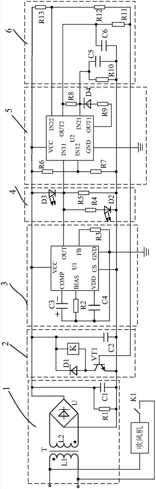
[0020] Such as figure 1 As shown, the infrared automatic hand dryer circuit of the present invention consists of a hair dryer, a power supply circuit 1, a control circuit 2 connected to the output end of the power supply circuit 1, a drive circuit 3 connected to the output end of the control circuit 2, and a drive circuit 3 The infrared transceiver circuit 4 connected to the output, the signal amplifying circuit 5 connected to the output of the infrared transceiver circuit 4, and the delay circuit 6 connected to the output of the signal amplifying circuit 5 are composed. The hair dryer is connected with the power circuit 1 .

[0021] The power supply circuit 1 is used to provide a power supply basis for subsequent circuits, which is composed of a transformer T, a diode bridge rectifier U, a capacitor C1 connected in series between the two output terminals of the diode bridge rectifier U, and connected in parallel with the capacitor C1 Composed of resistor R1. The two input e...


PUM


Abstract

The invention discloses an infrared automatic hand drier circuit. The infrared automatic hand drier circuit is characterized by comprises a blower, a power circuit (1), a control circuit (2) connected with the output end of the power circuit (1), a driving circuit (3) connected with the output end of the control circuit (2), an infrared transmitting and receiving circuit (4) connected with the output end of the driving circuit (3), a signal amplifying circuit (5) connected with the output end of the infrared transmitting and receiving circuit (4), and a time-delay circuit (6) connected with the output end of the signal amplifying circuit (5). The blower is connected with the power circuit (1). According to the infrared automatic hand drier circuit, the blower is controlled through infrared to dry hands, so that compared with a traditional paper wiping mode, the infrared automatic hand drier circuit can save a large amount of paper and achieve environmental protection and energy conservation.

Description

technical field [0001] The invention relates to a circuit, in particular to an infrared automatic hand dryer circuit. Background technique [0002] It is very inconvenient for people with wet hands for a period of time after washing their hands. In order to solve this problem, at present, paper towels for wiping hands are placed in the washrooms of some public places, and these paper towels can be used to dry hands after people wash their hands, which brings convenience to people. [0003] However, the large flow of people in public places leads to a large consumption of paper towels, resulting in a great waste of resources, which is not in line with the concept of energy conservation and emission reduction advocated by the current human society. Therefore, how to solve the above problems is an urgent task for people. Contents of the invention [0004] The purpose of the present invention is to solve the defect that people use paper towels to wipe their hands and cause a...

Claims


Application Information

Patent Timeline
Patent Type & Authority Applications(China)
IPC IPC(8): A47K10/48
Inventor 周小玲
Owner TONGXIANG HUIFENG ELECTRICAL APPLIANCE DIE CASTING PLANT
Why Eureka
Try Eureka