Automatic workpiece conveying device

A technology of automatic conveying device and workpiece, applied in the directions of transportation and packaging, loading/unloading, etc., can solve the problems of low efficiency and high labor intensity of workers, and achieve the effect of saving labor, reducing labor intensity and improving production efficiency.

Active Publication Date: 2015-01-07
宁波长华布施螺子有限公司
9 Cites 2 Cited by

AI-Extracted Technical Summary

Problems solved by technology

[0003] The technical problem to be solved by the present invention is to provide an automatic workpiece conveyi...

Abstract

The invention relates to an automatic workpiece conveying device which comprises a steel frame body. The steel frame body is of a cuboid frame structure formed by connecting stand columns, long cross beams and wide cross beams end to end. The parts at one end of the steel frame body and along the two stand columns of the steel frame body are each provided with a loading lifting device, the loading lifting devices are provided and connected with electrical apparatus control system boxes, inlets are formed in the bottoms of the loading lifting devices, a row of horizontal roller paths are fixedly arranged in front of the inlets in a connection mode, iron drum circulating boxes are installed in the loading lifting devices, a row of rails arranged along the long cross beams of the steel frame body are connected to outlets in the upper portions of the loading lifting devices, feeding trolleys are installed on the upper faces of the rails, a plurality of hoppers are hung on the lower faces of the rails, the outer sides of the two loading lifting devices are each fixedly provided with a pedestrian path, and handrails are installed on the outer sides of the pedestrian paths. The automatic workpiece conveying device is simple in structure, the structure of automatic loading and automatic feeding is adopted, full automatic production is achieved, the production effect is improved, the labor intensity of workers is lowered, and labor is saved.

Application Domain

Loading/unloading

Technology Topic

HandrailLower face +6

Image

  • Automatic workpiece conveying device
  • Automatic workpiece conveying device

Examples

  • Experimental program(1)

Example Embodiment

[0015] Example 1
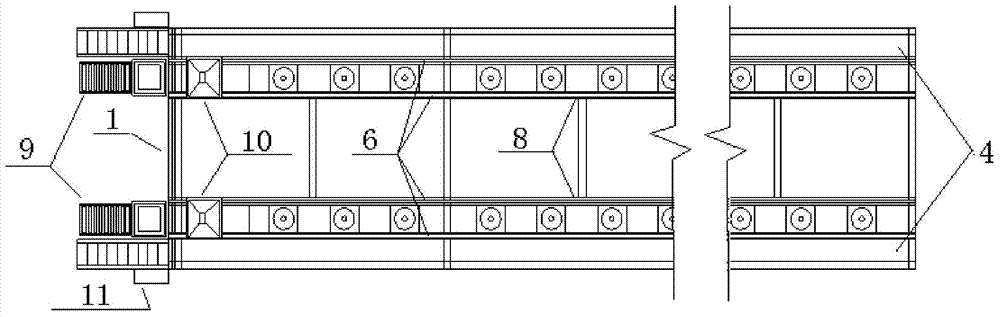
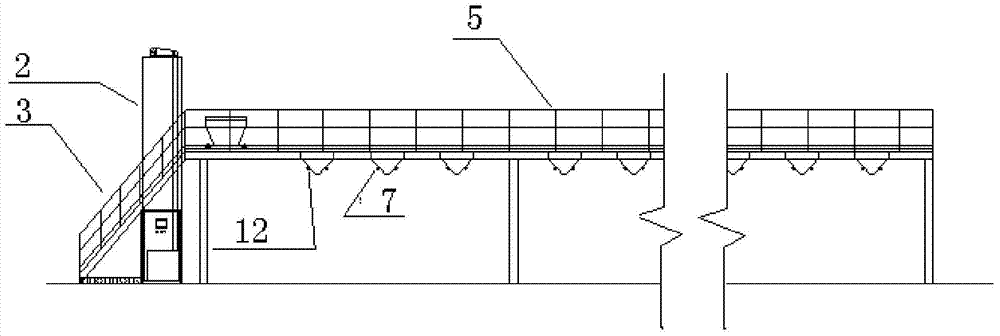
[0016] Such as Figure 1 ~ Figure 2 As shown, a workpiece automatic conveying device, which sends the parts to be processed through the automatic feeding conveyor line to the required station, including the steel frame main body 1, the feeding lifting device 2, the escalator 3, the pedestrian passage 4, and the handrail 5. , Track 6, hopper 7, wire trough 8, raceway 9, feeding trolley 10, electrical control system box 11, radio sensor switch 12 and other related accessories.
[0017] If the hopper alarm light of the 6th station hopper 7 flashes, it means that the hopper on the radio sensor switch 12 detects that the hopper has no material, and prepares for feeding.
[0018] Put the parts to be processed into the iron drum turnover box. The iron drum turnover drum is transported to the raceway 9 with a forklift, and the forklift exits. The iron barrel turnover box on the raceway 9 smoothly rolls into the feeding lifting device 2. Find the station that needs to be fed in the electrical control system box 11, press the 6th station start button in the automatic state, the feeding lifting device 2 will start to operate, and the iron drum turnover box will slowly rise on the feeding lifting device 2 and reach the end point Then, the work stops under the designation of the limit switch, and at the same time, the parts in the iron bucket turnover box are slowly poured into the feeding trolley 10, after being poured into the feeding trolley 10, the start time set in the PLC is reached, and the feeding trolley starts While walking, the iron bucket turnover box in the loading lifting device 2 runs backwards at the same time, descends to the end, and stops after touching the limit switch.
[0019] The feeding trolley 10 walks slowly on the laid track, and when it reaches the top of the 6th station hopper that needs to be fed, the photoelectric switch on the side of the trolley receives the specified information, the side door of the feeding trolley 10 will slowly lift, and the parts are automatically poured into the hopper 7 Inside, after the feeding trolley 10 finishes the parking time, the side door will slowly close, and the feeding trolley will slowly return to the original point after closing the side door, and stop after touching the limit switch.
[0020] The automatic feeding process is all over, and the hopper warning light is automatically extinguished, realizing the automatic conveying of parts processing.

PUM

no PUM

Description & Claims & Application Information

We can also present the details of the Description, Claims and Application information to help users get a comprehensive understanding of the technical details of the patent, such as background art, summary of invention, brief description of drawings, description of embodiments, and other original content. On the other hand, users can also determine the specific scope of protection of the technology through the list of claims; as well as understand the changes in the life cycle of the technology with the presentation of the patent timeline. Login to view more.

Similar technology patents

Photoelectric sensor for position of sun

InactiveCN101650173AEffective tracking range expandedSimple structure
Owner:WUHAN UNIV OF TECH

Magnetic cooling apparatus and control method thereof

ActiveUS20130180263A1simple structure
Owner:SAMSUNG ELECTRONICS CO LTD

Dual-Drivetrain of Power-Assist Vehicle

InactiveUS20100181130A1enhance uphill momentumsimple structure
Owner:CHOU WEN CHENG

Classification and recommendation of technical efficacy words

  • Simple structure
  • Improve production efficiency

New method and equipment for preparing vacuum glass faceplate

InactiveCN101050056AImprove production efficiencyImprove yield and mechanical strength
Owner:罗建超

Spliced-video generation method and device, terminal equipment and storage medium

ActiveCN109618222Aavoid subjectivityImprove production efficiency
Owner:BEIJING BYTEDANCE NETWORK TECH CO LTD

Device for mixing and preparing coating

InactiveCN104117308AImprove production efficiencyAvoid being unable to clean
Owner:丹阳市海信涂料化工厂
Why Eureka
Try Eureka