Method for achieving automatic positioning of cross section parallel hole for rock drilling machine rapidly and accurately

A rock drilling rig and automatic positioning technology, which is applied to the automatic control system of drilling, drilling equipment, earthwork drilling and production, etc., can solve the problems of complex working environment, slow solution speed, and complicated process of hydraulic rock drilling rigs, and achieve favorable The effect of intelligent control, strong real-time performance, and simple calculation process

Inactive Publication Date: 2015-01-07
YANSHAN UNIV
View PDF6 Cites 9 Cited by
  • Summary
  • Abstract
  • Description
  • Claims
  • Application Information

AI Technical Summary

Problems solved by technology

However, due to the complex working environment of the hydraulic rock drilling rig, and because the drilling boom system is a set of multi-degree-of-freedom mechanisms, when positioning the end of the drilling boom, it is necessary to perform kinematic forward and inverse analysis on the drilling boom system of the rock drilling rig
However, for multi-degree-of-freedom series mechanisms,

Method used


Image

  • Method for achieving automatic positioning of cross section parallel hole for rock drilling machine rapidly and accurately
  • Method for achieving automatic positioning of cross section parallel hole for rock drilling machine rapidly and accurately
  • Method for achieving automatic positioning of cross section parallel hole for rock drilling machine rapidly and accurately

Examples


Embodiment

[0038] Example: A certain type of hydraulic rock drilling rig

[0039] Using this type of hydraulic rock drilling rig to quickly and accurately realize the method of automatic positioning of parallel holes in the section of the rock drilling rig, the specific steps are as follows:

[0040] step 1:

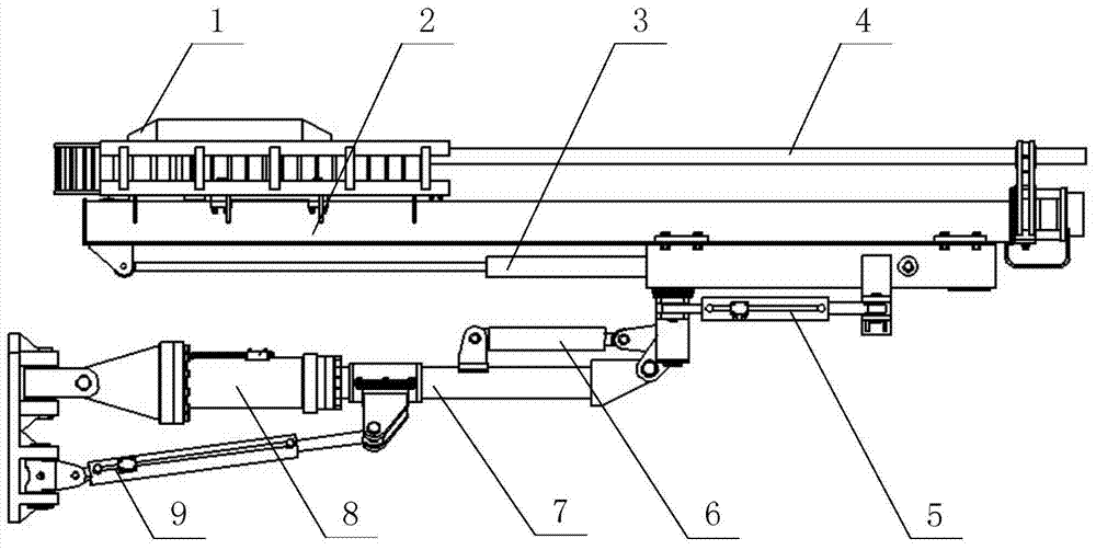
[0041] Analyze the structural composition of the drilling arm positioning mechanism of the hydraulic rock drilling rig and the actions of each mechanism. Such as figure 1 As shown, the drill boom positioning mechanism includes a power head 1, a thruster 2, a thruster compensation cylinder 3, a drill rod 4, a thruster swing cylinder 5, a thruster pitch cylinder 6, a boom 7, a thruster turning cylinder 8 and a drill arm The left and right luffing cylinders 9; the lifting and swinging actions of the drill boom are jointly driven by the left and right luffing cylinders 9 symmetrically arranged on the drill boom body; , Propeller pitching oil cylinder 6 and propeller overturning oil...


PUM


Abstract

The invention discloses a method for achieving automatic positioning of a cross section parallel hole for a rock drilling machine rapidly and accurately. The method for achieving automatic positioning of the cross section parallel hole for the rock drilling machine rapidly and accurately comprises the steps that the structural components of a drilling arm positioning mechanism of the hydraulic rock drilling machine and the movement of all mechanisms are analyzed, the joint coordinate system of the drilling arm positioning mechanism of the hydraulic rock drilling machine is established according to a structure model of a drilling arm system of the hydraulic rock drilling machine by means of the D-H method, the coordinate system of a drilling arm positioning system and connecting rod parameters are analyzed, and the functional relationships between the coordinates of a positioning tail end in a base coordinate system and all joint variables are calculated; cross section parallel hole regional planning for the hydraulic rock drilling machine is conducted; all the joint variables are solved; the pre-positioned position of the positioning tail end during drilling of the rock drilling machine is determined, the pre-positioned coordinates of the positioning tail end in the base coordinate system and all target joint variables are calculated, and a control module is driven in real time through a closed loop to adjust all hydraulic cylinders, so that whether the positioning tail end reaches a preset position is judged. By the adoption of the method for achieving automatic positioning of the cross section parallel hole for the rock drilling machine rapidly and accurately, the difficulty of solving the joint variables of the drilling arm system of the hydraulic rock drilling machine is greatly lowered.

Description

technical field [0001] The invention relates to the technical field of intelligent control of hydraulic rock drilling rigs, in particular to a method for quickly and accurately realizing automatic positioning of cross-sectional parallel holes. Background technique [0002] With the gradual maturity and application of rock excavation construction technology and advanced production technology, hydraulic rock drilling rig technology has made great progress, such as blasting in deep hole bench section, large aperture deep hole pre-splitting blasting, smooth surface blasting It has been widely used in rock drilling operations such as mine roof cutting and mining, trimming and slope protection for traffic construction, anchor cable holes and grouting holes. At present, in the process of rock drilling, blasting by drilling parallel holes in the tunnel section is the most widely used. However, in the process of drilling parallel holes, the accurate positioning of the drilling posit...

Claims


Application Information

Patent Timeline
IPC IPC(8): E21B47/09
CPCE21B44/00
Inventor 高英杰刘凯磊涂朝辉高大伟
Owner YANSHAN UNIV
Why Eureka
Try Eureka