Conveyor unloading part rear-mounted end hydraulic support

A technology of end hydraulic supports and unloading parts, which is applied in mine roof supports, mining equipment, earthwork drilling and mining, etc. It can solve problems such as failure to meet layout requirements, difficulty in left and right adjustment, and inability to use effectively, so as to reduce labor intensity of workers, Flexible, compact effects

Inactive Publication Date: 2015-01-07
SHENYANG TIAN AN TECH CO LTD
View PDF11 Cites 5 Cited by
  • Summary
  • Abstract
  • Description
  • Claims
  • Application Information

AI Technical Summary

Problems solved by technology

[0005] At present, some corresponding patent documents have disclosed mechanized end support devices, mainly including the Chinese patent "Roofway Caving End Support" with the announcement number CN201314239Y, and the Chinese patent "Self-moving end support" with the announcement number CN201288579Y. Head support ", publication number is CN101315031A Chinese patent " fully mechanized working face rail along end support ", announcement number is CN202673314U Chinese patent " fully mechanized mining face end support " and the announcement number designed by the inventor is CN203362199U The Chinese patent "Hydraulic support at the end of the fully mechanized mining face", these patents have proposed technical solutions to effectively solve the support problems for the end area of ​​the fully mechanized mining operation face and the end area of ​​the fully mechanized mining operation face with top coal caving. To a certain extent, it meets the requirements of the equipment installation, use and maintenance conditions of the fully mechanized mining face, and can ensure the required safety space and support effect in the end area; Difficult, it is only suitable for the rectangular roadway supported by bolts and anchor nets, and cannot be used effectively in the arched roadway, and most of them can only be used when the scraper conveyor and the transfer machine on the working face are overlapped by end unloading. When the connection form is cross-side unloading, the layout requirements cannot be met, and the use is limited

Method used


Image

  • Conveyor unloading part rear-mounted end hydraulic support
  • Conveyor unloading part rear-mounted end hydraulic support
  • Conveyor unloading part rear-mounted end hydraulic support

Examples


Embodiment Construction

[0025] The present invention will be further described in detail below in conjunction with the accompanying drawings and specific embodiments.

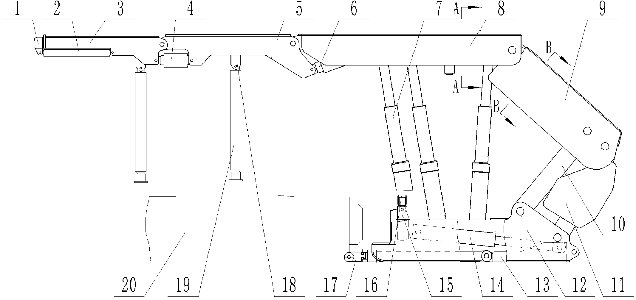
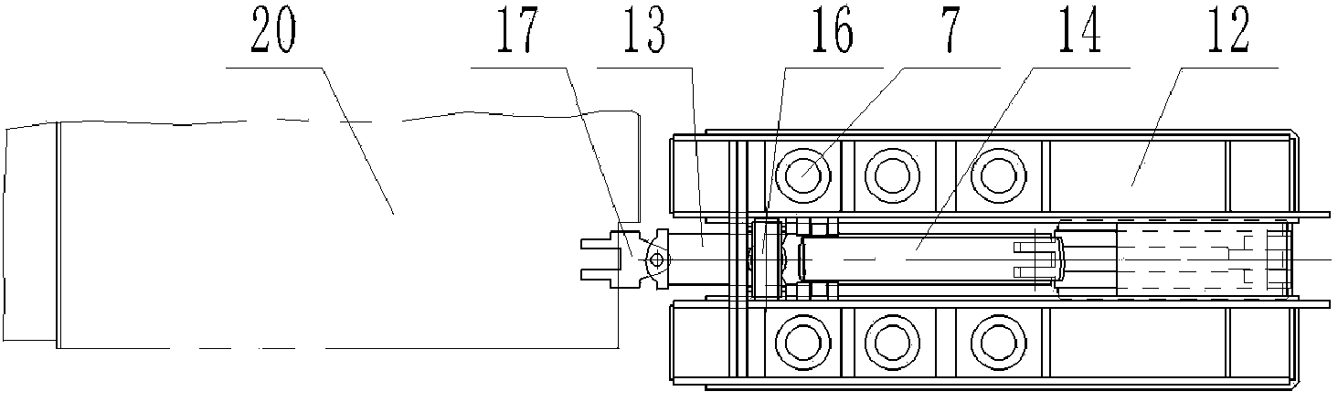
[0026] Such as Figure 1 to Figure 5 As shown, a post-mounted end hydraulic support of the unloading part of the conveyor includes a base 12, a top beam, a hydraulic column 7, a cover beam 9, and front and rear connecting rods. The top beam is composed of a middle top beam 5 and a rear top beam 8 ; For the purpose of ensuring that the present invention is stable and stable in support, the base 12 is hinged with one end of the shield beam 9 through the front and rear links respectively, and the base 12, the shield beam 9 and the front and rear links form a four-link Mechanism; the other end of cover beam 9 is hinged with one end of back top beam 8, and the other end of rear top beam 8 is hinged with the rear end of middle top beam 5, and between middle top beam 5 and back top beam 8 is provided with Middle roof beam hydraulic cylinder...


PUM


Abstract

The invention discloses a conveyor unloading part rear-mounted end hydraulic support, belonging to the mining machinery manufacture and application technology field. The conveyor unloading part rear-mounted end hydraulic support comprises a pedestal, a rear top beam, a hydraulic stand column, a caving shield, a front connection rod and a rear connection rod, the pedestal, caving shield, the front connection rod and the rear connection rod can form the four bar mechanism, the hydraulic stand column is jointed between the rear top beam and the pedestal, the middle of the pedestal is provided with a pushing hydraulic cylinder and a pushing rod, the front part of the pedestal is provided with a lifting pedestal hydraulic cylinder, wherein the conveyor unloading part rear-mounted end hydraulic support further comprises a middle top beam, the front end of the rear top beam is jointed to the rear end of the middle top beam, a middle top beam hydraulic cylinder is formed between the middle top beam and the rear top beam. The structure is compact, the design is reasonable, the support capability is strong, the stable performance is good, the end unloading or cross side unloading use requirement for the joint mode between the work surface scraper conveyer and the reversed loader can be satisfied and the work surface coal mining efficiency can be raised.

Description

technical field [0001] The invention belongs to the technical field of mining machinery manufacturing and application, and relates to a support device for the end area of ​​the mining working face in mining, in particular to a supporting device for the end area of ​​the working face, which can The hydraulic support at the rear end of the unloading part of the conveyor that moves with the advancement of mining in the working face. Background technique [0002] The end area of ​​the mining face is the area where the ground pressure of the roadway and the stress caused by mining are superimposed and elevated, and there is support pressure around the mining face and on both sides of the roadway. The most severe and difficult-to-manage area on the roof; in addition, there are more equipment arranged in the end area, and it is close to the top cutting line of the working face, so it is difficult to support, so it is also an accident-prone area. [0003] Since the end of the minin...

Claims


Application Information

Patent Timeline
IPC IPC(8): E21D23/04
CPCE21D23/04E21D23/063E21D23/08
Inventor 曹伟张天顺金灿东
Owner SHENYANG TIAN AN TECH CO LTD
Why Eureka
Try Eureka