Ultrahigh pressure pilot operated relief valve

A pilot-operated relief valve, ultra-high pressure technology, applied to valve details, safety valves, balance valves, etc., can solve problems such as short service life, overflow valve scrapping, frequent replacement, etc., achieve good wear resistance and prolong service life The effect of improving the service life and the strength of the valve seat

Inactive Publication Date: 2015-01-07
XIHUA UNIV
View PDF5 Cites 9 Cited by
  • Summary
  • Abstract
  • Description
  • Claims
  • Application Information

AI Technical Summary

Problems solved by technology

[0005] The purpose of the present invention is: in order to overcome the shortcomings of the entire relief valve scrapped and frequently replaced due to the rapid wear of the pilot valve seat in the ultra-high pressure system during the use of the traditional pilot relief valve, to invent a The pilot-operated relief valve structure of the ultra-high pressure system solves the problems of poor reliability and short service life of ordinary pilot-operated relief valves used in ultra-high pressure systems

Method used


Image

  • Ultrahigh pressure pilot operated relief valve
  • Ultrahigh pressure pilot operated relief valve

Examples


Embodiment 1

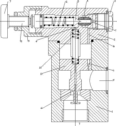
[0016] Embodiment 1: as figure 1 In the ultra-high pressure pilot relief valve shown, the ultra-high pressure fluid enters the main valve (1) from the inlet (P), and passes through the orifice (a), the channel (b) and the radial and axial holes (c) on the screw plug. ) and the center hole of the separated valve seat act on the pilot valve core (5). Compression elastic force, the pilot spool (5) presses the separate valve seat (4), and is in the closed state, the pressure in the upper and lower chambers of the main spool (11) is equal (static pressure transmission), under the action of the main valve spring (10) , the main valve core is also pressed tightly on the main valve seat, the main valve port is closed, the inlet (P) and the oil return port (T) are blocked, and there is no overflow. When the pressure at the inlet (P) increases, the fluid is applied to the pilot valve. When the hydraulic pressure on the core (5) is greater than the pre-compressed elastic force on the pr...

Embodiment 2

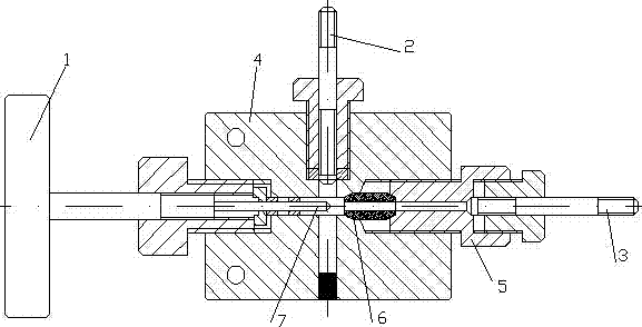
[0018] Example 2: see figure 2 Ultra-high pressure stop valve, the screw plug (5) is threadedly connected with the valve body (4), the separate valve seat (6) is pressed on the stop valve body (4) through the screw plug (5), and the handle (1) is turned , so that the valve stem pushes the valve needle (7) to press against the separate valve seat (6), thereby cutting off the incoming flow from the pipeline (3), thereby realizing the function of a stop valve, turning the handle (1) in the opposite direction to open Valve port, fluid can flow from line (3) to line (2).

[0019] The separated valve seat (4) is made of materials with high impact strength and good wear resistance. On the one hand, the strength of the valve seat can be improved and the service life of the ultra-high pressure globe valve can be extended. On the other hand, when the valve seat is worn out, only the valve seat needs to be replaced. , without replacing the entire stop valve, very suitable for ultra-hig...


PUM


Abstract

The invention discloses an ultrahigh pressure pilot operated relief valve, consisting of a main valve and a pilot valve. The pilot valve is composed of a pressure-regulating hand wheel, a regulating bolt, a pilot valve pressure-regulating spring, a pilot valve element, a high-strength separating type valve seat and a plug. The separating type valve seat is provided with a center hole and two conical ends, and is tightly pressed to the pilot valve body by the plug that is in threaded connection with the pilot valve body, and the plug is provided with radial and axial holes. The pilot valve element and the high-strength separating type valve seat are matched to form rigidity seal. The ultrahigh pressure pilot operated relief valve adopts the separating valve seat, is simple in structure, convenient to install, maintain and replace, overcomes the problems that the common pilot operated relief valve is poor in reliability and short in service life when being used in an ultrahigh pressure system.

Description

technical field [0001] The invention relates to the field of fluid transmission control, in particular to a high-pressure and superhigh-pressure overflow valve, which can be used for pressure regulation and control in high-pressure and superhigh-pressure fluid transmission control. Background technique [0002] The overflow valve is a widely used pressure control valve. Its basic working principle is to compare the hydraulic pressure generated by the fluid pressure on the valve core with the spring force. When the hydraulic pressure is greater than the pressure regulating spring force, the valve port opens and Start to overflow; when the hydraulic pressure is less than the pressure regulating spring force, the valve port is closed to stop the overflow, so that the system pressure is basically stable at a certain set value, and the pressure control is realized. [0003] The relief valve is divided into a direct-acting relief valve and a pilot relief valve. The direct-acting...

Claims


Application Information

Patent Timeline
Patent Type & Authority Applications(China)
IPC IPC(8): F15B13/02F16K17/04
CPCF15B13/023F16K17/10F16K31/1221F16K31/124
Inventor 雷玉勇陶欢万霞蒋代君刘克福杨涵张丽陈玄唐炼
Owner XIHUA UNIV
Why Eureka
Try Eureka