Ultra-high pressure flow controller

A flow controller and ultra-high pressure technology, applied in valve details, safety valves, engine components, etc., can solve the problems of short life, poor performance, large natural decline, etc., to ensure service performance and process performance, small flow adjustment. Good characteristics and reasonable structure settings

Active Publication Date: 2015-01-07
ZHEJIANG AOXIN INSTR
View PDF5 Cites 5 Cited by
  • Summary
  • Abstract
  • Description
  • Claims
  • Application Information

AI Technical Summary

Problems solved by technology

[0003] At present, when the water injection oil production process is applied in oilfields in western my country such as Xinjiang Oilfield, Turpan-Hami Oilfield and offshore platforms, when the water injection pressure at the wellhead is less than 35MPa, water cannot be injected or the geologically allocated water injection volume cannot be completed, resulting in low oil production rate and natural decline. big-amplitude
The traditional flow controller generally works below 25MPa, and the pressure difference between the front and back of the flow controller is not high, most of which are below 3MPa. When applied to UHV conditions, it exposes low pressure difference, poor performance, short life, and safety. Defects such as low performance, poor small flow regulation characteristics, etc.

Method used


Image

  • Ultra-high pressure flow controller
  • Ultra-high pressure flow controller
  • Ultra-high pressure flow controller

Examples


Embodiment Construction

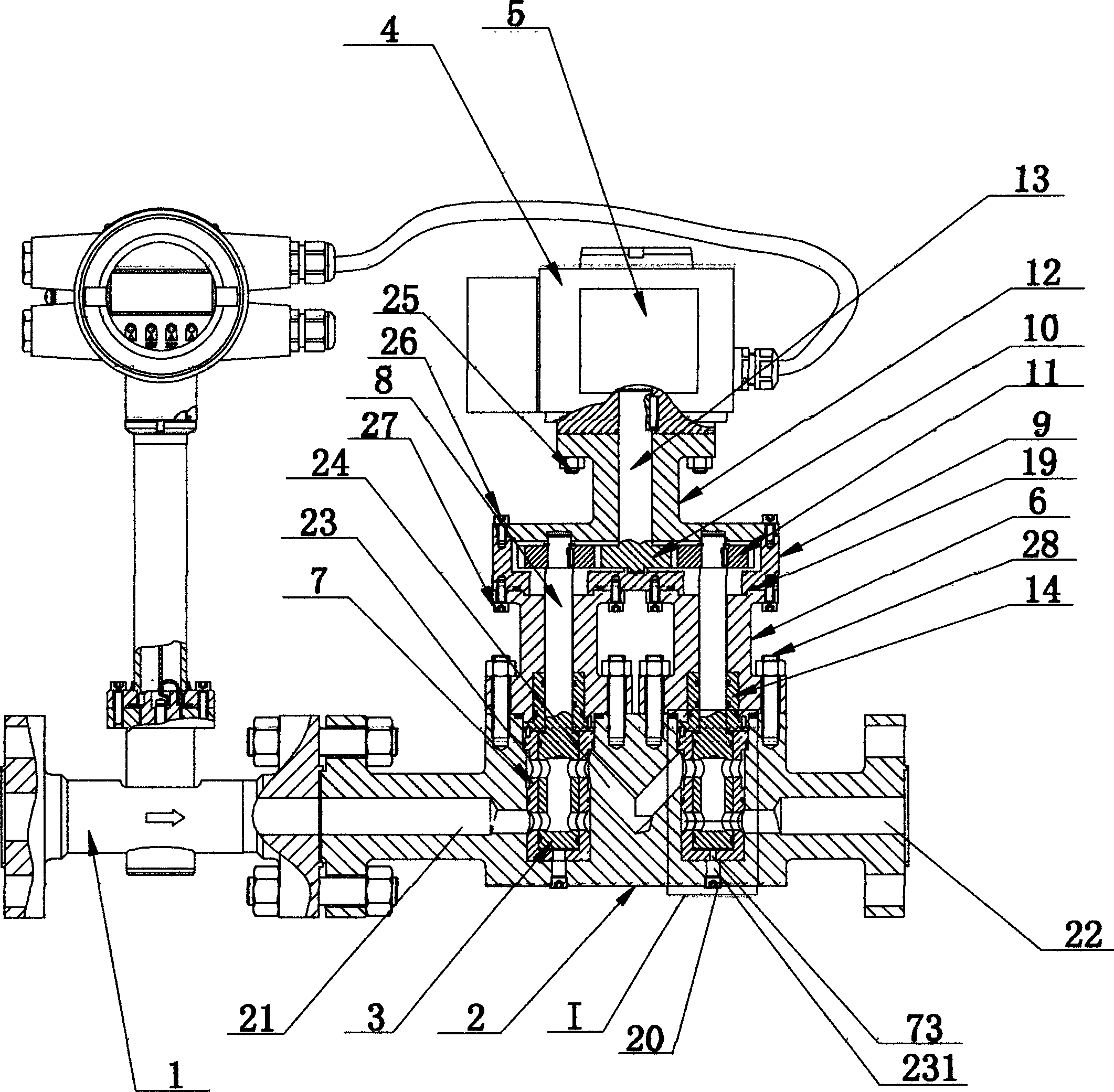
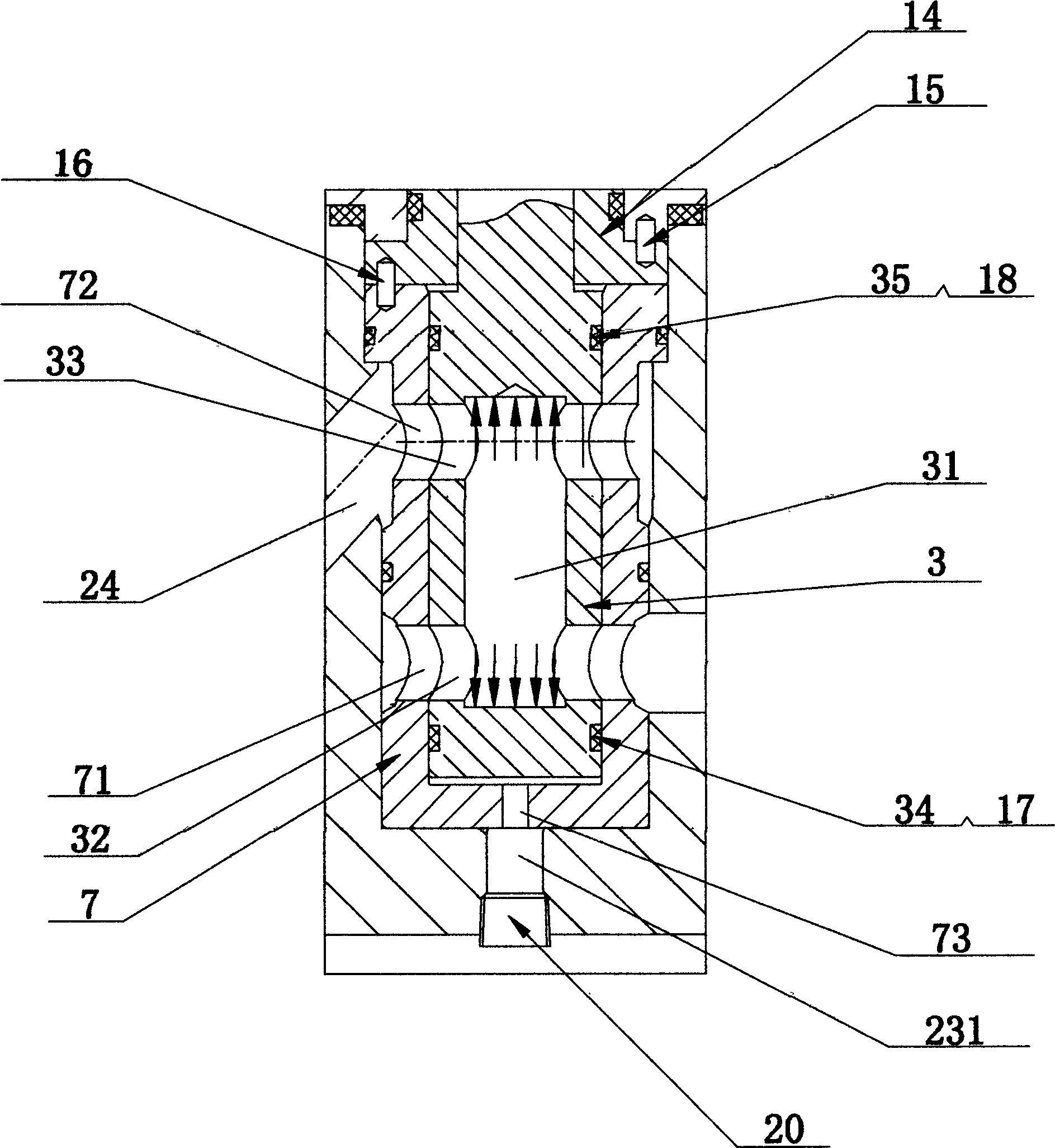
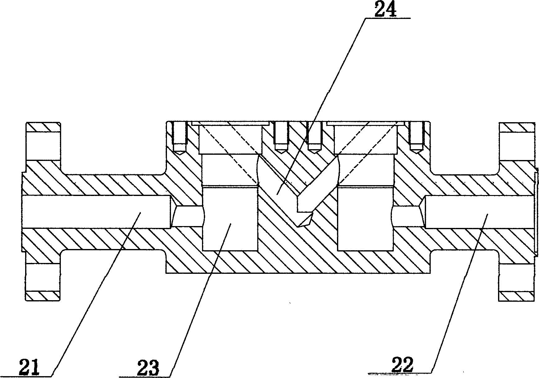
[0021] see figure 1 , figure 2 with image 3 , a UHV flow controller disclosed in the present invention, comprising a flow meter 1, a valve body 2, a valve core 3, an electric actuator 4, and a digital regulator 5, and the upper end of the valve body 2 is detachably provided with a valve cover 6 , the left and right ends of the valve body 2 are respectively provided with a fluid inlet 21 and a fluid outlet 22, and the middle part of the valve body 2 is vertically provided with two valve inner chambers 23, and a longitudinal valve inner chamber 23 is arranged between the two valve inner chambers A fluid channel 24 with a "V"-shaped cross-section, a sleeve 7 is installed in each valve inner cavity 23, and a valve core 3 is inserted into each sleeve 7, that is, a sleeve 7 is sleeved on each valve core 3 , the upper end of each spool 3 is integrally provided with a valve stem 8, the upper end of the valve cover 6 is detachably provided with a gear box 9, the gear box 9 is provi...


PUM


Abstract

The invention discloses an ultra-high pressure flow controller comprising a flowmeter, a valve body, valve cores, an electric actuating mechanism, a digital regulator and a bonnet. A fluid passageway is formed between two inner chambers in the valve body. The longitudinal section of the fluid passageway is in the V shape. A valve rod is arranged at the upper end of each valve core in the integral manner. A gear box is arranged at the upper end of the bonnet and internally provided with a drive gear. Two lateral ends of the drive gear are provided with driven gears meshed with the drive gear. Central lines of the driven gears and those of the valve rods below the driven gears coincide. The upper ends of the valve rods are connected with the driven gears upon the same to form linkage. A frame is detachably arranged at the upper end of the gear box. The electric actuating mechanism is connected with the upper end of the frame. A connecting shaft is arranged between the electric actuating mechanism and the drive gear. The lower end of the connecting shaft is fixedly connected with the drive gear, and the upper end of the connecting shaft is connected with the electric actuating mechanism. The connecting shaft is driven by the electric actuating mechanism to rotate. The ultra-high pressure flow controller is reasonable in structural design, excellent in performance, long in service life and high in safety.

Description

technical field [0001] The invention relates to the technical field of flow controllers, in particular to an ultra-high pressure flow controller. Background technique [0002] As an instrument product, the flow controller is widely used in the flow automatic control system in the chemical industry, petroleum, metallurgy, electric power and other industries. The flow controller is generally composed of a flow meter, a digital regulator, an electric actuator, and a regulating valve. [0003] At present, when the water injection oil production process is applied in oilfields in western my country such as Xinjiang Oilfield, Turpan-Hami Oilfield and offshore platforms, when the water injection pressure at the wellhead is less than 35MPa, water cannot be injected or the geologically allocated water injection volume cannot be completed, resulting in low oil production rate and natural decline. big-amplitude. The traditional flow controller generally works below 25MPa, and the pres...

Claims


Application Information

Patent Timeline
Patent Type & Authority Applications(China)
IPC IPC(8): F16K17/20F16K31/53
CPCF16K17/20F16K31/53
Inventor 胡建田汪剑英范则富范叔卫陈福钏陈通照陈承凯白帆施玉辉
Owner ZHEJIANG AOXIN INSTR
Why Eureka
Try Eureka