Supercharge Your Innovation With Domain-Expert AI Agents!

Visual sensor on-site calibration device and calibration method

A visual sensor, field calibration technology, applied in measurement devices, optical devices, instruments, etc., can solve the problems of cumbersome calibration process, limited number of calibration points and accuracy, and complicated implementation, achieving simple device structure and simplified mathematical model. , the effect of easy operation

Inactive Publication Date: 2017-02-01
HEBEI UNIVERSITY OF SCIENCE AND TECHNOLOGY
View PDF6 Cites 0 Cited by
  • Summary
  • Abstract
  • Description
  • Claims
  • Application Information

AI Technical Summary

Problems solved by technology

These three calibration methods all require sophisticated calibration auxiliary equipment, the calibration process is cumbersome, and not suitable for on-site calibration
In response to this problem, someone proposed a calibration method based on a plane reference object, which simplifies the calibration equipment and is suitable for on-site calibration. However, the position of the laser light bar and the plane calibration reference object needs to be changed many times during each calibration, and the calibration process is relatively cumbersome. It is necessary to establish a three-dimensional local world coordinate system on the reference object. Every time the reference object moves to a position, the conversion matrix from the local world coordinate system to the world (camera) coordinate system at this position must be calculated, which increases the complexity of calibration.
Later, in order to simplify the calibration procedure, a new method for calibrating the structural parameters of the line-structured light vision sensor was proposed by using the distance constraints between the feature points with known distances on the one-dimensional target, because this method needs to combine multiple one-dimensional The fixed position of the three-dimensional target is placed, and it is more complicated to realize on site, and the number and accuracy of calibration points are limited.

Method used


Image

  • Visual sensor on-site calibration device and calibration method
  • Visual sensor on-site calibration device and calibration method
  • Visual sensor on-site calibration device and calibration method

Examples


Embodiment Construction

[0015] The structure and operation of the present invention are illustrated with reference to the accompanying drawings.

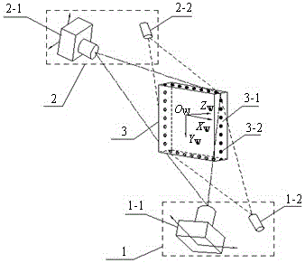
[0016] An on-site calibration device for a visual sensor is composed of a first structure sensor 1 , a second structure sensor 2 and a calibration target 3 .

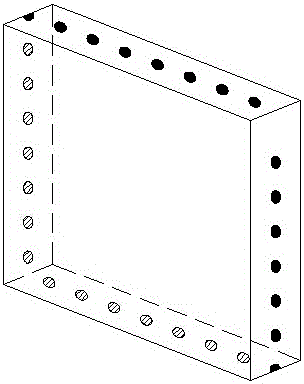
[0017] The calibration target 3 is placed at the measurement station on the measurement site, the first structure sensor 1 is placed at the lower left of the calibration target 3 , and the second structure sensor 2 is placed at the upper right of the calibration target 3 . The main structure of the calibration target 3 is a flat square target body 3-1, and several target dots 3-2 are arranged as required on the long axes of the four rectangular surfaces of the square target body 3-1. Dot 3-2 forms a measurement plane, and it is necessary to ensure that the measurement plane is at the measurement station during on-site calibration. The structure of calibration target 3 is as follows figure 2 As sh...


PUM


Abstract

The invention discloses a field calibration device for a visual sensor and a method for carrying out field calibration through the field calibration device. The field calibration device is composed of a first structure sensor (1), a second structure sensor (2) and a calibration target (3). The calibration target (3) is arranged at a measurement station on a measurement field, the first structure sensor (1) is arranged below the left side of the calibration target (3), and the second structure sensor (2) is arranged below the right side of the calibration target (3). The field calibration device is simple in structure and easy to operate, calibration points are accurately obtained, a mathematic model is accordingly simplified, and the field calibration device is suitable for field calibration.

Description

technical field [0001] The invention relates to a calibration device and a calibration method, in particular to a device and a calibration method for on-site calibration of a line-structure vision sensor when using a line-structured light vision sensor for contour line measurement. Background technique [0002] Object contour measurement technology is becoming more and more important in the fields of quality control, industrial inspection, reverse engineering, CAD / CAE and medical diagnosis. With the rapid development of computer technology, optics and optoelectronics technology, various optical profile measurement methods have been widely used. The profile measurement method based on line structured light vision sensor is one of the important ones. It uses a linear structured light projector to irradiate the object to be measured, forming a bright light band on the surface of the object, and uses a CCD camera to obtain the image of the light band, and processes and analyzes...

Claims


Application Information

Patent Timeline
Patent Type & Authority Patents(China)
IPC IPC(8): G01B11/24
Inventor 黄风山陈丽黄永建张付祥
Owner HEBEI UNIVERSITY OF SCIENCE AND TECHNOLOGY
Features
  • R&D
  • Intellectual Property
  • Life Sciences
  • Materials
  • Tech Scout
  • Unparalleled Data Quality
  • Higher Quality Content
  • 60% Fewer Hallucinations
Learn More