
Method for installing large-caliber permanent magnet direct-current torque motor

A technology of permanent magnet DC and torque motors, which is applied in the direction of electromechanical devices, manufacturing motor generators, electrical components, etc. It can solve problems such as difficult to meet installation requirements, and achieve the effects of convenient installation, reduced overall size, and reliable use

Active Publication Date: 2015-01-07
SHANGHAI INST OF OPTICS & FINE MECHANICS CHINESE ACAD OF SCI
View PDF6 Cites 10 Cited by
  • Summary
  • Abstract
  • Description
  • Claims
  • Application Information

AI Technical Summary

Problems solved by technology

For thin-walled parts with a hollow rotating shaft, and the motor rotor is required to be directly installed on the rotating shaft, since there is no space between the motor rotor and the rotating shaft to install a fixed bracket, this method is difficult to meet the installation requirements

Method used


Image

  • Method for installing large-caliber permanent magnet direct-current torque motor
  • Method for installing large-caliber permanent magnet direct-current torque motor
  • Method for installing large-caliber permanent magnet direct-current torque motor

Examples


Embodiment Construction

[0029] The present invention will be further described below in conjunction with the accompanying drawings and embodiments, but the protection scope of the present invention should not be limited thereby.

[0030] In this embodiment, the motor rotor is fixed on the rotating shaft first, and then the rotating shaft equipped with the motor rotor is installed in the motor stator.

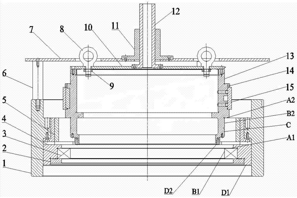
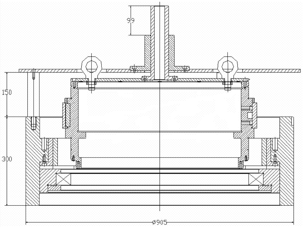
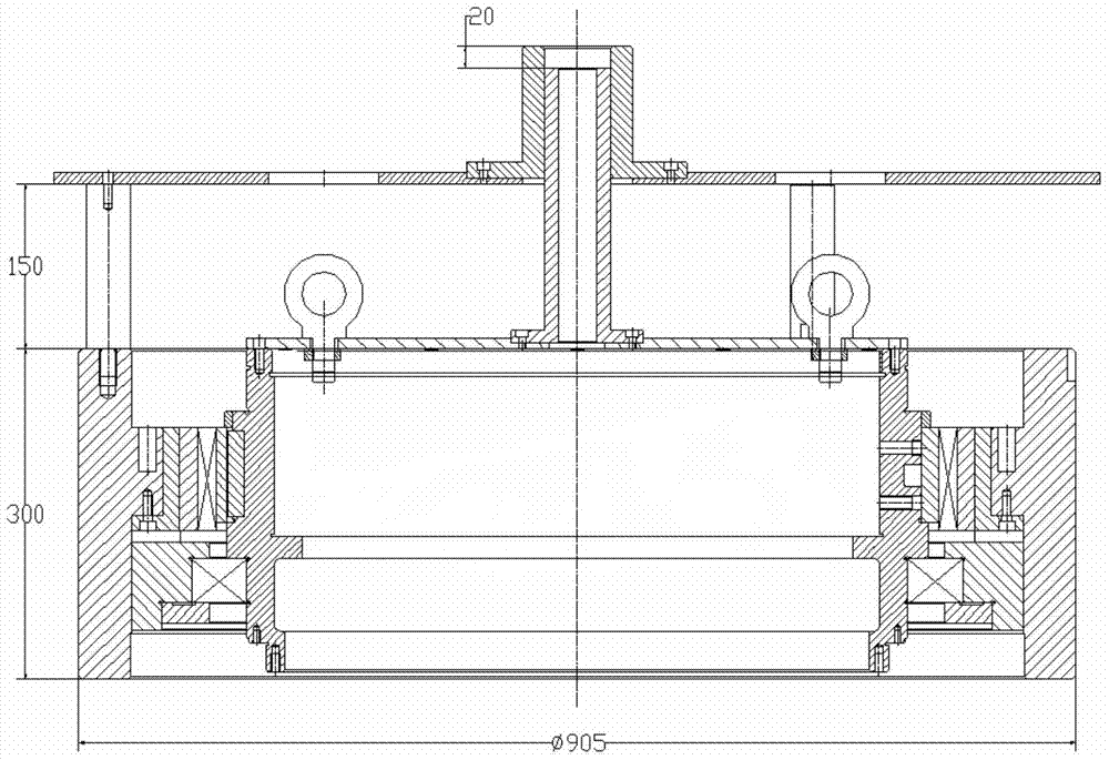
[0031] see first figure 1 , figure 1 It is a structural diagram of the installation method of the split type torque motor in the present invention. Depend on figure 1 It can be seen that the motor stator 5 is fixed in the rotating seat 1, and the bearing seat 4 is installed in the rotating seat 1, and the ball bearing 3 is installed in the bearing seat 4, and is fixed by the bearing cover plate 2. The function of the ball bearing 3 is to support and fix the rotating shaft 13 . The rotating shaft 13 is a hollow shaft, and the motor rotor 15 is installed outside the rotating shaft 13 and fixed with a...


PUM


Abstract

The invention discloses a method for installing a large-caliber permanent magnet direct-current torque motor. The method includes the following steps: (1) a motor stator and a ball bearing are firstly installed in a rotating base; (2) a motor rotor is installed outside a rotating shaft; (3) a guide sleeve fixed to a small disc penetrates through a center through hole in a large disc, and then the large disc is arranged on the outer end faces of three supporting columns; (4) the inner diameter of a guide base is matched with the outer diameter of the guide sleeve, and the guide base is fixed to the large disc; (5) the rotating shaft is downwards slowly moved through a hoisting tool along the guide base under the effect of gravity and slightly rotated around the guide base for enabling the shaft shoulder end face of the rotating shaft to be matched with the inner ring end face of the ball bearing; (6) the distance between the outer end face of a bearing block and the outer end face of the rotating shaft is measured to the required position size, and installation of the torque motor is completed. The method has the advantages of being simple and easy to implement.

Description

technical field [0001] The invention relates to a split-type permanent magnet direct-current torque motor, in particular to a method for installing a large-diameter split-type permanent-magnet direct-current torque motor. Background technique [0002] Permanent magnet DC torque motor is a low-speed DC servo motor that outputs large torque at low speed, and is widely used in low-speed, high-torque rotating occasions. Because the permanent magnet DC torque motor can be directly driven, the speed change mechanism is omitted, and the running accuracy is improved. The user installs the motor into the shaft system that needs to rotate, which can greatly reduce the space occupied by the entire equipment and make the system structure more compact. The commutation design of this kind of motor is divided into two types: brushed and brushless. The difference is that the commutation of the brushed DC motor has always been realized by contacting the graphite brush with the annular commut...

Claims


Application Information

Patent Timeline
IPC IPC(8): H02K15/00
Inventor 王利娟孙建锋李保良刘立人
Owner SHANGHAI INST OF OPTICS & FINE MECHANICS CHINESE ACAD OF SCI
Learn More