Relay path allocation system and method supporting flow optimization and application awareness
A technology of traffic optimization and path allocation, which is applied in the field of network communication and can solve problems such as unspecified technical solutions
Active Publication Date: 2015-01-07
NORTHEASTERN UNIV
4 Cites 5 Cited by
AI-Extracted Technical Summary
Problems solved by technology
However, how to effectively organize relay servers and allocate high-quality relay paths for end-to-end data transmission, tha...
Method used
[0051] The network mapping table contains a series of network location groups. The network location group includes domain identifiers and network address prefixes. The network address prefixes can represent one or more subnets, metropolitan area networks, and autonomous systems. In an actual network, many terminals are very close in network connection, such as terminals in the same company or...
Abstract
The invention provides a relay path allocation system and method supporting flow optimization and application awareness and belongs to the technical field of network communication. Bottom layer network information provided by an application layer flow optimization server is utilized, a control server carries out effective organization on a relay overlapping network formed by relay servers according to the bottom layer network topological information, and a relay overlapping network topological model has the characteristics that scalability is high and the relay overlapping network topological model can perceive a bottom layer physical network; the control server obtains multiple types of transmission performance of the relay overlapping network by using the detection performance of the relay servers, thereby having the capacity for application awareness; routing expenses, transmission performance, load rates and other factors are comprehensively considered in a path cost evaluation method for relay paths, so that the relay path allocation system and method have excellent performance in the aspect of selecting high-quality relay paths and can flexibly balance loads among the relay servers.
Application Domain
Data switching networks
Technology Topic
Transmission performancePath cost +13
Image
Examples
- Experimental program(1)
Example Embodiment
[0048] The specific embodiments of the present invention will be described in detail below with reference to the accompanying drawings.
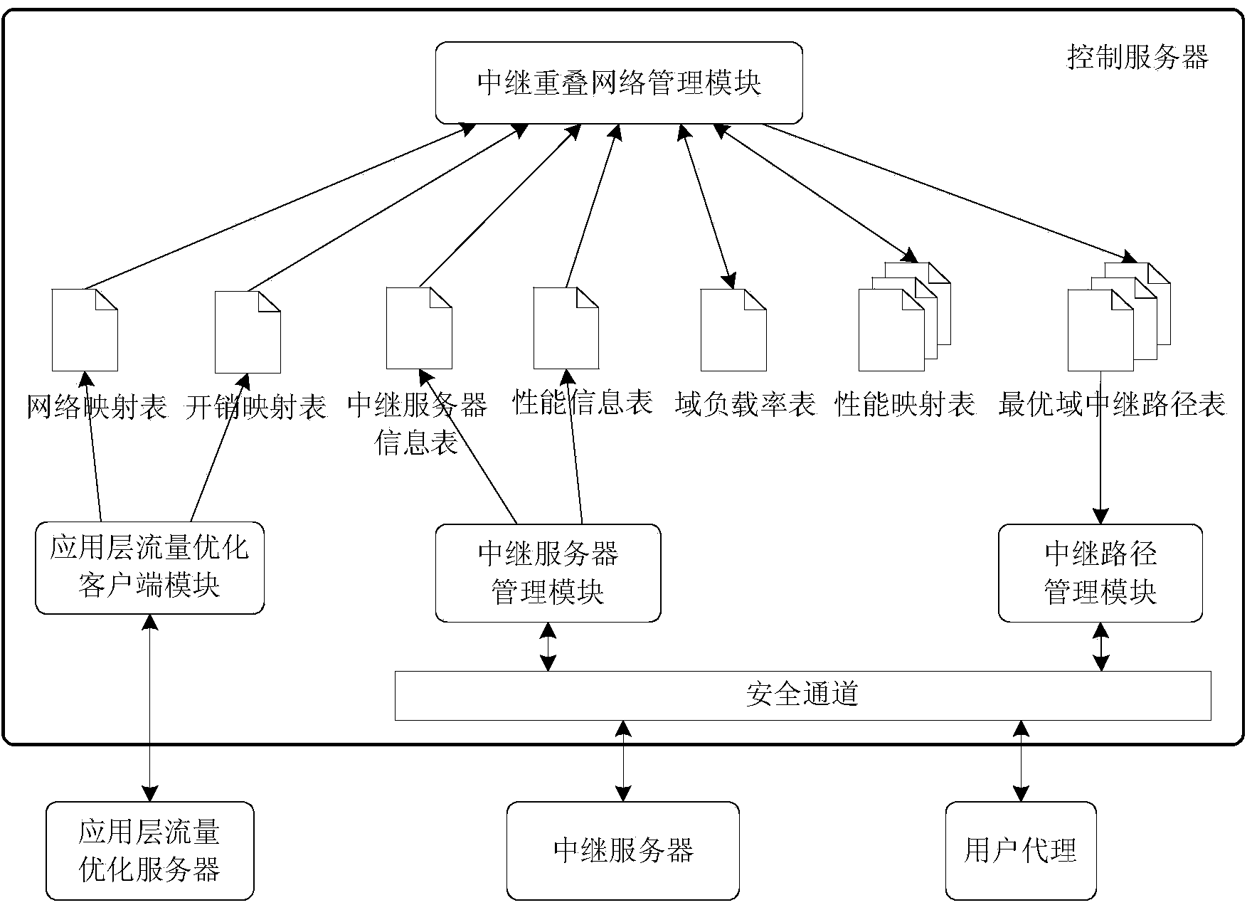
[0049] The relay path allocation system supporting traffic optimization and application awareness in this embodiment, such as figure 1 shown, including application-layer traffic optimization servers, control servers, and relay servers.
[0050] The application layer traffic optimization server is used to obtain network information, and organize the network information into the form of a network mapping table and an overhead mapping table. The application layer traffic optimization server can obtain network information in various ways, such as routing protocols, static configuration policies, dynamic network information, and even third-party content providers through external interfaces.
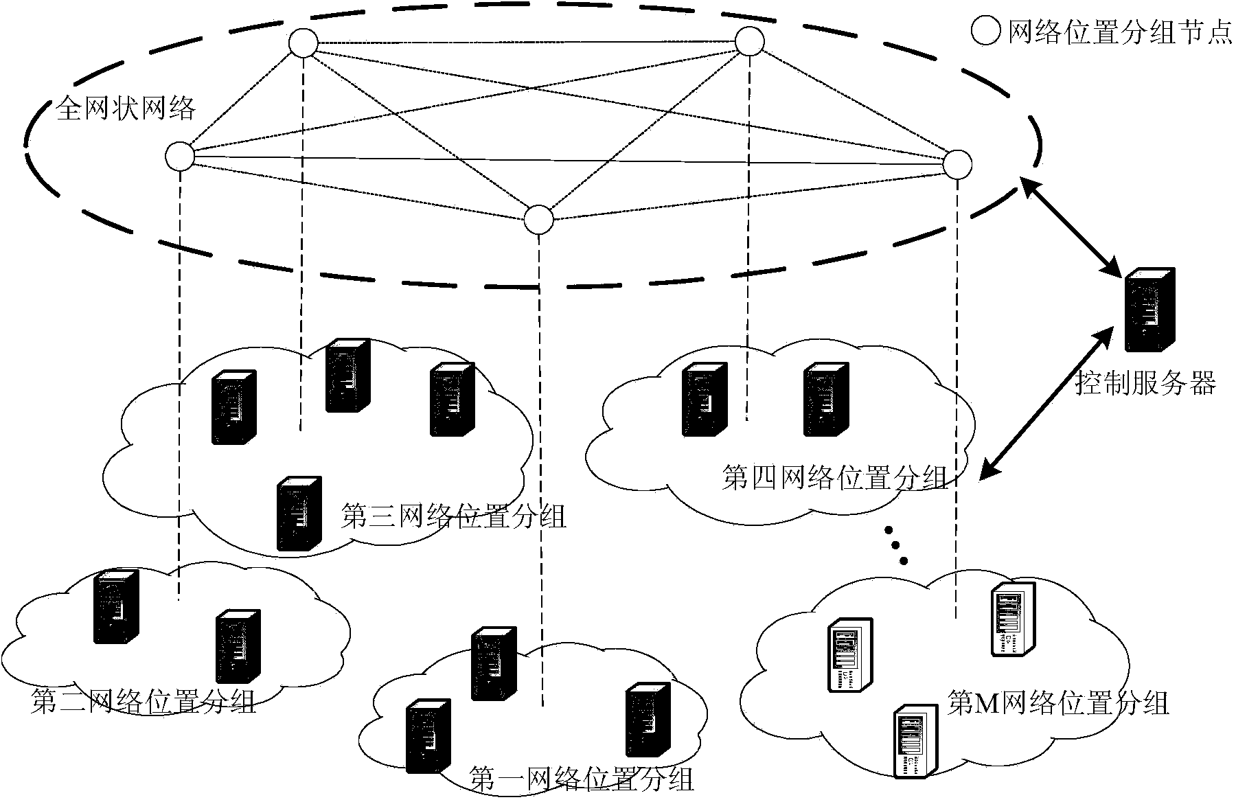
[0051] The network mapping table contains a series of network location groupings that include domain identifiers, network address prefixes, and network address prefixes can represent one or more subnets, metropolitan area networks, and autonomous systems. In an actual network, many terminals are very close to each other on the network connection, such as terminals in the same company or university. By abstracting these neighboring terminals into a network location grouping, greater scalability can be achieved without losing important network topology information. By grouping network locations, the application layer traffic optimization server provides network termination aggregation based on network topology or other network attributes in an indirect network-independent manner.
[0052] The cost map contains routing costs between network location packets. Routing cost refers to the end-to-end cost of a unit of traffic from source to destination. It is of general significance. Network operators can perform internal calculations based on their own policies, such as the physical distance between networks, routing hops, or routing costs. The application layer traffic optimization server uses the form of routing overhead to formulate the priority between network location groups, so as to achieve the purpose of modifying the network resource consumption pattern.
[0053] The application layer traffic optimization server divides the network information into a network mapping table and an overhead mapping table. It does not change for a long time, but the overhead mapping table reflecting the dynamic state information of the network may change in a short time.
[0054] The relay server in this embodiment adopts the relay service repeater described in claim 4 of the Chinese patent application with the application number of 201410196986.4, "A Multipath Transmission System and Method Based on Application Layer Relay". The relay server constructs a list of relay servers according to the registration success response message or the connection keep-alive message, and performs a performance detection process. Overlay links between relay servers typically consist of multiple physical links; in addition to overlay traffic, non-overlay traffic will also use the same physical link. Therefore, the relay server cannot control or manage the network resources of the IP layer, and can only rely on the detection mechanism to obtain the performance information of the overlay link with other relay servers. Using the performance detection process, the relay server can obtain the dynamic transmission performance of the overlay link with other relay servers, and report the detected transmission performance information to the control server via the connection keep-alive message.
[0055] The relay server needs a set of detection operators to evaluate the transmission performance of the overlay link with other relay servers. The main function of these detection operators is to give a quantitative value of the quality of a coverage link according to the corresponding transmission performance measure. These quantitative values are relative and are only used for comparison with other quantitative values obtained by the same detection operator. By default, the relay server supports two detection operators: the delay detection operator and the packet loss ratio detection operator, which are used to detect the delay and packet loss ratio of the overlay link between relay servers, respectively. In actual deployment, new performance metrics can be added according to the specific transmission requirements of upper-layer applications, such as throughput, delay jitter, etc., and even new performance metrics can be defined for certain types of upper-layer applications. It is enough to support the corresponding detection operator. An implementation example of the delay detection operator and the packet loss rate detection operator is given below.
[0056] The delay detection operator periodically sends a delay detection packet to each relay server in the relay server list, and calculates and obtains a round-trip delay sample of the associated coverage link. An exponentially weighted moving average of the round-trip delay sample values can be used as the delay estimate for the overlay link. R_Delay ij Represents the relay server R i and R j The delay evaluation value of the coverage link between the two is calculated according to formula (1):
[0057] R_Delay ij =αR_Delay ij +(1-α)New_Sample ij (1)
[0058] Among them, New_Sample ij Represents the newly obtained round-trip delay sample, the parameter α is the sliding weight, the default value is 0.9, which represents the estimated delay value R_Delay ij 10% is taken from the latest round-trip delay sample value.
[0059] The packet loss rate detection operator periodically sends consecutive n consecutive messages to each relay server in the relay server list. 1 (The default value is 10) packet loss rate detection packets, and calculate to obtain a packet loss rate sample of the associated overlay link. The calculated packet loss rate sample value gives the two-way packet loss probability, and the one-way packet loss probability can be estimated under the premise that the packet loss rate is symmetrical. The packet loss rate estimate of the coverage link adopts the latest n 2 (The default value is 10) The mean calculation of packet loss rate sample values.
[0060]The control server in this embodiment adopts the relay service controller described in claim 3 of the Chinese patent application "A Multipath Transmission System and Method Based on Application Layer Relay" with the application number of 201410196986.4. The control server reads the network mapping table and the overhead mapping table from the application layer traffic optimization server, maps the relay servers to network location groups according to the network mapping table, and organizes the relay servers according to the underlying bearer network topology information. Through the network mapping table and the cost mapping table, the control server can learn the network information of the underlying network infrastructure, so as to be able to allocate the underlying network-aware relay path with the minimum routing cost to the user agent with data transmission requirements. The control server obtains the transmission performance between the relay servers from the relay server, and obtains the transmission performance between the network location packets according to the network mapping table and the transmission performance between the relay servers. The control server obtains the load rate of the relay server from the relay server, and obtains the domain load rate of the network location grouping according to the network mapping table and the load rate of the relay server. According to the overhead mapping table, the transmission performance between network location packets, the domain load rate of network location packets, and the received relay path allocation request message from the user agent or third-party signaling server, the control server can The optimal relay path is allocated for the data transmission between them.
[0061] Divided according to functions, the control server includes an application layer traffic optimization client module, a relay server management module, a relay overlay network management module and a relay path management module.
[0062] The application layer traffic optimization client module periodically obtains the network mapping table and the overhead mapping table from the application layer traffic optimization server. The application layer traffic optimization client module needs to know the address of the application layer traffic optimization server. There are many ways for the application-layer traffic optimization client module to obtain the address of the application-layer traffic-optimization server, for example, using DNS query to obtain the HTTP(S) URI of the application-layer traffic-optimization server.
[0063] The relay server management module manages and maintains the registration and status information of all relay servers in the domain: sends a performance query message to the registered relay server to query its performance information, including processor capacity, storage capacity, and network bandwidth; period It sends a status query message to the available relay server to query its current load information, including the number of relay paths, processor usage, and network bandwidth usage. The relay server management module stores the performance and load information of the relay server in the relay server information table. During the relay server registration or connection keep-alive process, the relay server management module selects n randomly or according to a certain strategy within each network location group. 3 (n 3 ≥1) registered relay server and pass its address information to the relay server. The relay server management module acquires the transmission performance between the relay server and other relay servers from the relay server, and stores it in the performance information table.
[0064] The relay overlay network management module maps each registered relay server to a network location group according to the network mapping table, and the network location group can cover the IP address of the relay server. The mapping method is to match the IP address of the relay server with the network address prefixes of all network location groups in the network mapping table. There may be multiple matching network address prefixes. The longest matching principle is adopted, and the longest matching network address prefix is selected. The network location grouping corresponding to the network address prefix. Obviously, each network location grouping may contain multiple relay servers. In this way, the control server divides the relay servers into network location groups, and the network location groups represent a group of addresses that are geographically close and have similar routing policies. Therefore, the control server divides the relay servers according to the underlying bearer network topology information. To organize, group relay servers that are geographically close and have similar routing policies into a group, and can implement the same relay path allocation policy for them, so that the relay overlay network topology composed of relay servers can be well adapted to The underlying bearer network.
[0065] like figure 2 As shown, the control server organizes the relay overlay network into a two-tier model. The lower layer is a discrete network composed of relay servers. The control server communicates with each relay server and maintains the performance, load and other information of a single relay server. The upper layer is a full mesh network composed of network location grouping nodes, which abstracts multiple relay servers belonging to the same network location grouping into a single node, and the control server maintains the communication between any two network location grouping node pairs. Transmission performance information. Assuming that the number of relay servers is N, and the number of network location grouping nodes is M, obviously M<
[0066] The relay overlay network management module maintains performance information between groups of network locations. The transmission performance between two network location groupings can be calculated as an average of the corresponding transmission performances between the plurality of relay server pairs located in the two network location groupings. By default, the relay overlay network management module manages and maintains two transmission performance metrics between network location packets: delay and packet loss rate, which are stored in the delay mapping table and packet loss rate mapping table, respectively. PID_Delay ij Indicates the network location packet PID i and PID j Delay evaluation value between, PID_Lossrate ij Indicates the network location packet PID i and PID j The estimated value of the packet loss rate between the two is calculated according to the following formulas:
[0067] PID _ Delay ij = avg R k ∈ PID i , R m ∈ PID j ( R _ Delay km ) - - - ( 2 )
[0068] PID _ Lossrate ij = avg R k ∈ PID i , R m ∈ PID j ( R _ Lossrate km ) - - - ( 3 )
[0069] Among them, R_Delay km Represents the relay server R k and R m delay estimate between, R_Lossrate km Represents the relay server R k and R m The estimated value of the packet loss rate between .
[0070] According to the relay server information table and the network mapping table, the relay overlay network management module calculates the domain load rate for each network location grouping, and stores it in the domain load rate table. PID_Loadrate i Indicates the network location packet PID i The domain load rate, by PID i The average load rate of all included relay servers is calculated, namely:
[0071] PID _ Loadrate i = avg R k ∈ PID i ( R _ Loadrate k ) - - - ( 4 )
[0072] Among them, R_Loadrate k Represents the relay server R k load rate.
[0073] According to the network mapping table, overhead mapping table, domain load rate table and multiple performance mapping tables, the relay overlay network management module calculates and obtains the optimal domain based on multiple transmission performance between any source network location grouping and destination network location grouping The relay path is stored in the corresponding optimal domain relay path table. The optimal domain relay path table is divided into the delay optimal domain relay path table and the packet loss rate optimal domain relay path table. A domain relay path is a path between a source network location packet and a destination network location packet via zero or more other network location packets, consisting of the domain identifier of the network location packet. When the network mapping table, the overhead mapping table, the domain load rate table or the corresponding performance mapping table changes, the relay overlay network management module regenerates the optimal domain relay path table.
[0074] After receiving the relay path allocation request message from the user agent or the third-party signaling server, the relay path management module generates the optimal IP relay path according to the optimal domain relay path table. The IP relay path is a path between the source end and the destination end via zero or more relay servers, consisting of IP addresses.
[0075] The relay path allocation method supporting traffic optimization and application awareness in this embodiment, such as image 3 shown, including the following steps:
[0076] 1) During the relay server registration or connection keep-alive process, select a group of relay servers, transfer the address information of the selected relay server to the relay server, and obtain the relationship between it and other relay servers from the relay server. The transmission performance between relay servers is stored in the performance information table; the transmission performance between relay servers includes delay and packet loss rate. In actual deployment, new performance metrics can be added according to the specific transmission requirements of upper-layer applications, such as throughput , delay jitter, etc., and even define new performance metrics for certain types of upper-layer applications;
[0077] 2) Query the performance information and load information of the relay server and store them in the relay server information table; the performance information includes the processor capacity, storage capacity and network bandwidth; the load information includes the number of relay paths, the processor utilization rate and the network bandwidth usage;
[0078] 3) Periodically read the network mapping table and the overhead mapping table from the application layer traffic optimization server;
[0079] 4) According to the network mapping table, map each registered relay server to a network location grouping, and the mapping method is to match the IP address of the relay server with the network address prefixes of all network location groups in the network mapping table, using the most According to the principle of long matching, select the network location group corresponding to the longest matching network address prefix;
[0080] 5) According to the network mapping table and the performance information table, calculate and obtain the transmission performance between the network location packets, and store in the corresponding performance mapping table, and the performance mapping table is divided into a delay mapping table and a packet loss rate mapping table;
[0081] 6) According to the network mapping table and the relay server information table, calculate the domain load rate for each network location grouping, and store it in the domain load rate table;
[0082] 7) According to the network mapping table, overhead mapping table, domain load rate table and multiple performance mapping tables, calculate and obtain the optimal domain relay path based on multiple transmission performances between any source network location grouping and destination network location grouping, and stored in the corresponding optimal domain relay path table; the optimal domain relay path table is divided into the delay optimal domain relay path table and the packet loss rate optimal domain relay path table; the domain relay path is the source the path between the network location packet and the destination network location packet via zero or more other network location packets, consisting of the domain identifier of the network location packet;
[0083] For each specified transmission performance, for any source network location grouping and destination network location grouping, the relay overlay network management module calculates the path cost of all domain relay paths between the source network location grouping and the destination network location grouping, and assigns the path cost to the The domain relay path with the least cost is regarded as the optimal domain relay path based on the specified transmission performance between the source network location packet and the destination network location packet. Experimental results show that the coverage path via a single relay node can provide similar performance to the optimal coverage path via multiple relay nodes in most cases. Therefore, when calculating the optimal domain relay path, the relay overlay network management module can limit the source network location grouping and the destination network location grouping via at most k (k>=1) other network location groupings, on this basis The domain relay path with the smallest path cost is regarded as the optimal domain relay path based on the specified transmission performance between the source network location packet and the destination network location packet.
[0084]The relay path allocation process should comprehensively consider multiple factors, including routing overhead, transmission performance, network location grouping, or load information of relay servers. It can not only combine routing policies, apply preferred performance metrics, but also avoid individual relay servers or certain relay servers. network location packets are overloaded. Therefore, when calculating the optimal domain relay path, the calculation method of the path cost of the domain relay path is very important.
[0085] Path cost includes path routing overhead cost and path transmission performance cost. Represents source network location grouping and destination network location grouping A domain relay path between PID - P PID n 0 → PID n m + 1 = ( PID n 0 , PID n 1 , . . . , PID n m , PID n m + 1 ) , m(m≥0) is the domain relay path The number of other network location packets via. Indicates the domain relay path The path cost of , is defined as the following formula:
[0086] PCost PID n 0 → PID n m + 1 = a 1 × PPATH _ Route cos t PID n 0 - PID n m + 1 + a 2 × PPATH _ QoS PID n 0 - PID n m + 1 - - - ( 5 )
[0087] Among them, a 1 and a 2 is a configuration parameter that satisfies a 1 +a 2 =1; Indicates the domain relay path The path routing overhead cost is the sum of routing overheads between two adjacent network location packets on the domain relay path; Indicates the domain relay path The path transmission performance cost.
[0088] Routing networks are usually not able to optimize multiple performance metrics simultaneously, for example, a path with a small delay may have a large packet loss rate. Therefore, the path transmission performance is only calculated based on a single performance metric in the implementation process, that is, the path transmission performance cost can be the path delay cost, the path packet loss rate cost, or other newly introduced according to the specific transmission requirements of the upper-layer application. Transmission performance metrics. The path delay cost is the sum of the delays between two adjacent network location packets on the domain relay path. The packet loss rate performance metric of the path obeys the multiplicative relationship, Indicates the domain relay path The path packet loss rate cost is calculated according to the following formula:
[0089] PPATH _ Lossrate PID n 0 → PID n m + 1 = 1 - Π 0 ≤ i ≤ m ( 1 - PID _ Lossrate n i n i + 1 ) - - - ( 6 )
[0090] In addition to the path routing overhead cost and the path transmission performance cost, the path cost can also include the path load rate cost, namely:
[0091] PCost PID n 0 → PID n m + 1 = a 1 × PPATH _ Route cos t PID n 0 → PID n m + 1 + a 2 × PPATH _ QoS PID n 0 → PID n m + 1 + a 3 × PPATH _ Loadrate PID n 0 → PID n m + 1 - - - ( 7 )
[0092] Among them, a 1 , a 2 and a 3 is a configuration parameter that satisfies a 1 +a 2 +a 3 =1; Indicates the domain relay path The path load rate cost is the maximum value of the domain load rate of the network location grouping on the domain relay path.
[0093] In addition to the path routing overhead cost and the path transmission performance cost, the path cost can also include the path relay cost. The reason is that the relay server consumes its own processing capability, network bandwidth and other resources in the process of providing the relay function, and also inevitably introduces additional processing delay, thereby increasing the transmission delay of the data reaching the receiving end. The calculation formula of path cost is as follows:
[0094] PCost PID n 0 → PID n m + 1 = a 1 × PPATH _ Route cos t PID n 0 → PID n m + 1 + a 2 × PPATH _ QoS PID n 0 → PID n m + 1 + a 3 × n × RC - - - ( 8 )
[0095] Among them, a 1 , a 2 and a 3 is a configuration parameter that satisfies a 1 +a 2 +a 3 =1; n is the domain relay path The number of network location groups that provide relay services through, when m ≥ 1, n=m, when m=0, n=1; RC represents the cost of the relay server to provide the relay function for a data stream Relay cost; that is, the path relay cost is proportional to the number of network location packets that provide the relay service through which the domain relay path passes.
[0096] In addition to the path routing overhead cost and the path transmission performance cost, the path cost can also include the path load rate cost and the path relay cost, namely:
[0097] PCost PID n 0 → PID n m + 1 = a 1 × PPATH _ Route cos t PID n 0 → PID n m + 1 + a 2 × PPATH _ QoS PID n 0 → PID n m + 1 + a 3 × PPATH _ Loadrate PID n 0 → PID n m + 1 + a 4 × n × RC - - - ( 9 )
[0098] Among them, a 1 , a 2 , a 3 and a 4 is a configuration parameter that satisfies a 1 +a 2 +a 3 +a 4 =1.
[0099] 8) After receiving the relay path allocation request message from the user agent or the third-party signaling server, the optimal IP relay path is generated according to the optimal domain relay path table; the IP relay path is determined by the source and destination. Paths between peers via zero or more relay servers, consisting of IP addresses;
[0100] Generate the optimal IP relay path according to the optimal domain relay path table, such as Figure 4 shown, including the following steps:
[0101] (1) Take out the application type, source IP address src_ip and destination IP address dst_ip from the relay path allocation request message;
[0102] (2) According to the network mapping table, the source IP address src_ip and the destination IP address dst_ip are respectively mapped to the source network location grouping according to the longest matching principle and destination network location grouping
[0103] (3) Determine the preferred transmission performance according to the application type, and find the corresponding optimal domain relay path table according to the preferred transmission performance;
[0104] (4) Obtain the source network location grouping from the optimal domain relay path table and destination network location grouping optimal domain relay path between
[0105] (5) If the optimal domain relay path Exclude source network location grouping and destination network location grouping grouping from the source network location without grouping via other network locations and destination network location grouping Select the one with the smaller domain load rate among the two, and randomly select a relay server R that maps to the network location grouping selected , the optimal IP relay path is determined by the source IP address, the selected relay server R selected IP address and destination IP address.
[0106] (6) If the optimal domain relay path Exclude source network location grouping and destination network location grouping In addition to grouping PIDs via one or more other network locations mid , grouping PIDs for each other network location via mid , randomly select a relay server mapped to the network location grouping, and the optimal IP relay path consists of the source IP address, the IP addresses of one or more selected relay servers, and the destination IP address.
[0107] Although the specific embodiments of the present invention have been described above, those skilled in the art should understand that these are only examples, and various changes or modifications may be made to these embodiments without departing from the principles and principles of the present invention. substance. The scope of the present invention is limited only by the appended claims.
PUM


Description & Claims & Application Information
We can also present the details of the Description, Claims and Application information to help users get a comprehensive understanding of the technical details of the patent, such as background art, summary of invention, brief description of drawings, description of embodiments, and other original content. On the other hand, users can also determine the specific scope of protection of the technology through the list of claims; as well as understand the changes in the life cycle of the technology with the presentation of the patent timeline. Login to view more.