Nail gel UV lamp and control method thereof

A control method and nail lamp technology, applied in the field of beauty, can solve problems such as unfavorable manicure solutions, inability to judge manpower, and inability to adapt to various manicure needs, so as to save internal space, facilitate internal wiring, and reduce production.

Active Publication Date: 2015-01-07
GUANGZHOU RISING DRAGON ELECTRONICS & PLASTICS TECH
View PDF7 Cites 3 Cited by
  • Summary
  • Abstract
  • Description
  • Claims
  • Application Information

AI Technical Summary

Problems solved by technology

From the time when the hand is taken out of the manicure lamp to the time it is put back into the manicure lamp, the paint is not baked during this period. The existing manicure lamp cannot judge whether the manpower is taken out and put back again during the work process, and cannot record effective baking. Time is not conducive to the design of precise nail art solutions, and it ca

Method used


Image

  • Nail gel UV lamp and control method thereof
  • Nail gel UV lamp and control method thereof
  • Nail gel UV lamp and control method thereof

Examples


Example Embodiment

[0040] Embodiment one

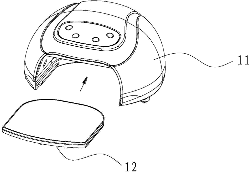
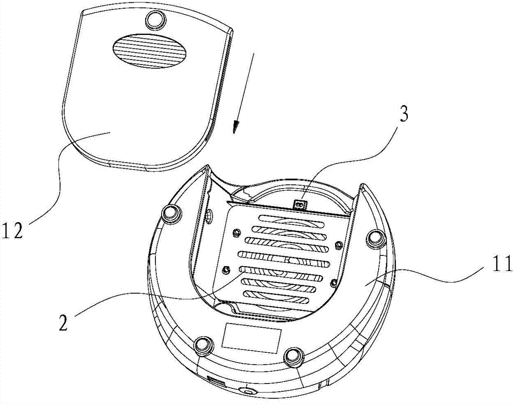
[0041] The manicure lamp has a shell, and the shell includes an upper shell 11 and a bottom plate 12. The upper shell 11 is arched, and the bottom plate 12 is inserted into the bottom of the upper shell 11. The upper shell 11 and the bottom plate 12 form a baking cavity, and the heating element 2 is installed on the top of the baking cavity.

[0042] The heating element 2 includes LED lamps and UV lamps.

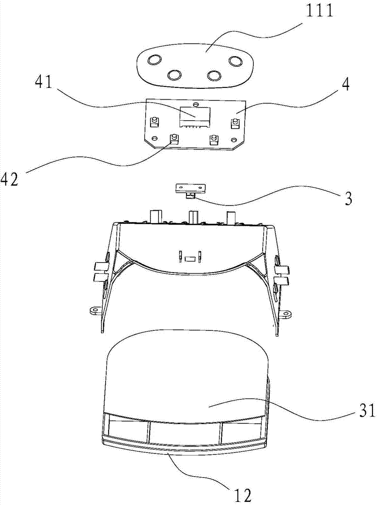
[0043] The sensor 3 is an infrared probe, and the infrared probe is integrated with an infrared emitter and an infrared detector. The sensor 3 is arranged on the top of the inner wall of the opening of the baking cavity, and the reflector 31 is a mirror surface, covering the upper surface of the bottom plate 12. 31 is opposite.

[0044] Also includes a control board 4, the control board 4 is electrically connected to the sensor 3, the controller, the LED display 41 and the switch module 42, the LED display 41 is used to display the current working mo...

Example Embodiment

[0063] Embodiment two

[0064] The difference between embodiment two and embodiment one is:

[0065] The working mode of the timer is to start counting up with 0, and count until the set duration, and the LED display 41 simultaneously displays the changing state of the current time with the time rhythm of adding 1 in seconds.

Example Embodiment

[0066] Embodiment three

[0067] The difference between embodiment three and embodiment one is:

[0068] In process a), if the hand is taken out from the manicure lamp, the timer stops timing, and the LED display 41 displays the current breakpoint time value. After a delay of 3 seconds, the heating element 2 is automatically turned off.


PUM


Abstract

The invention relates to a nail gel UV lamp and a control method of the nail gel UV lamp. The method comprises the steps that when detecting that a human hand stretches into a drying cavity, an inductor outputs a signal representing that the human hand stretches into the drying cavity to a controller, the controller starts a heating unit, and a counter starts timing; on this basis, if the human hand withdraws from the drying cavity, the heating unit is turned off, and the timer records the interruption time and stops timing; on this condition, if the human hand stretches into the drying cavity again in a set delay time, the heating unit is turned on again, and the timer continues timing from the interruption time; if the human hand does not stretch into the drying cavity again in the set delay time, the heating unit keeps in a turn-off state, and the timer resets. A user does not need to operate a nail printer in the drying process, it is only required that the human hand is placed into or taken out of the drying cavity normally, and the nail gel UV lamp can automatically conduct induction; the nail printer has a time delay memory function, the non-drying time of the human hand outside the nail gel UV lamp can be automatically eliminated, and the effective drying time can be recorded and accumulated.

Description

technical field [0001] The invention relates to the field of beauty treatment, in particular to a nail lamp and a control method. Background technique [0002] During the manicure process, after applying nail polish on the nails, it is necessary to use a nail lamp to bake the paint. With the continuous improvement of nail art technology and the continuous enrichment of nail art methods, if the materials used in nail art are diverse, the baking schemes required for various nail art methods are different. [0003] However, at present, the nail lamp has a single working mode, and only has simple functions such as on and off. During the manicure process, sometimes it is necessary to take the hands out of the nail lamp for observation. If the baking is completed, it is not necessary to put it back into the nail lamp again. If it is not finished, it needs to be put back into the nail lamp for baking again. From the time when the hand is taken out of the manicure lamp to the time...

Claims


Application Information

Patent Timeline
IPC IPC(8): H05B37/02
CPCY02B20/40
Inventor 戴忠果谢世书谢旭锋
Owner GUANGZHOU RISING DRAGON ELECTRONICS & PLASTICS TECH
Why Eureka
Try Eureka