Method for manufacturing laminated film
A manufacturing method, a technology for laminating films, applied in chemical instruments and methods, lamination, layered products, etc., can solve problems such as air bubble mixing, and achieve the effect of inhibiting mixing
- Summary
- Abstract
- Description
- Claims
- Application Information
AI Technical Summary
Problems solved by technology
Method used
Image
Examples
Embodiment approach 1
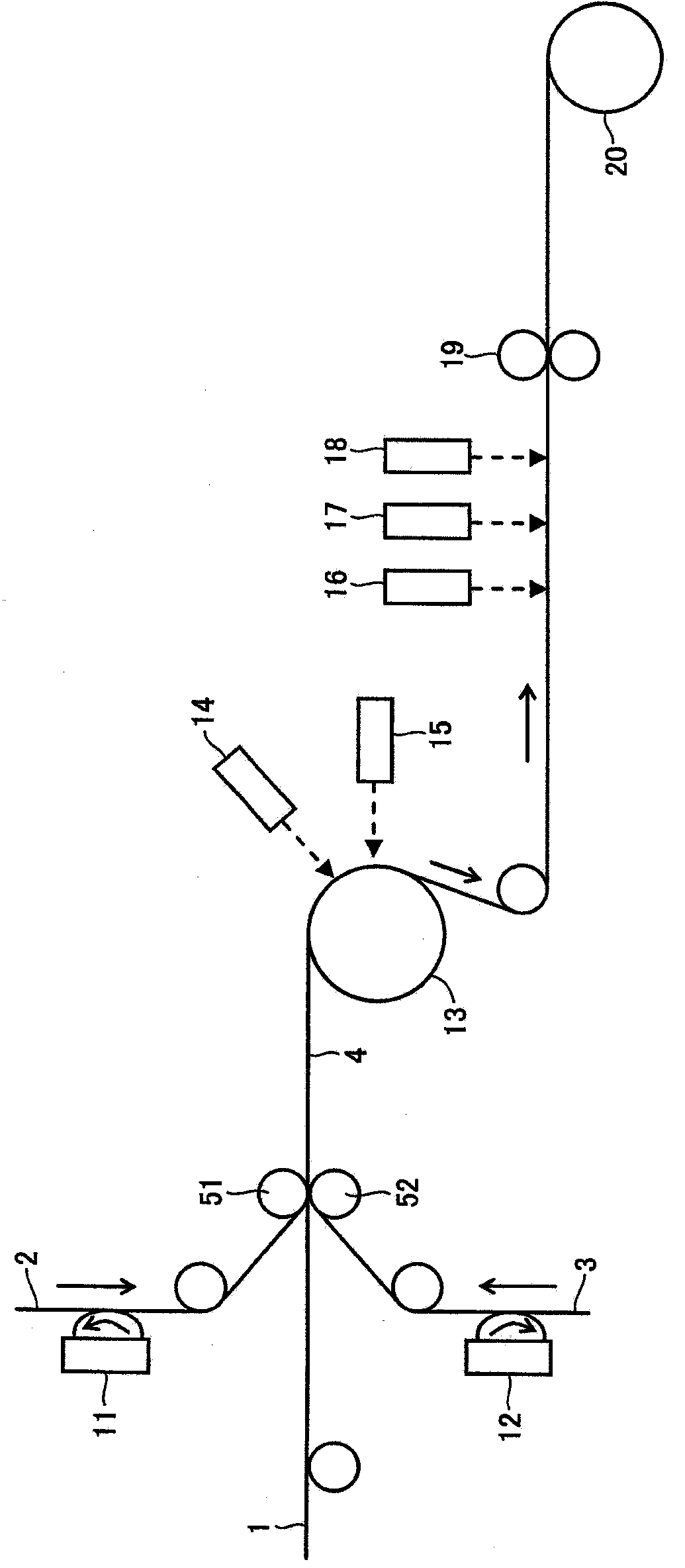
[0148] In this embodiment, the laminated film is manufactured from one optical film and two transparent films. In addition, in the adhesive coating step, the adhesive is applied to one side of each of the two transparent films, and in the pasting step, the adhesive of the two transparent films is mixed with the adhesive. In a state where both surfaces of the optical film are in contact with each other, the optical film and the transparent film are sandwiched between the pair of bonding rollers to bond each other.
[0149] Next, the manufacturing method of the present embodiment will be described with reference to the drawings. figure 1 It is a schematic diagram showing the structure of the whole apparatus used in the manufacturing method of this embodiment.
[0150] figure 1 In the manufacturing device of the laminated film shown in , adhesive coating devices 11 and 12 for coating adhesive on one side of the transparent films 2 and 3 are arranged in sequence along the convey...
Embodiment approach 2
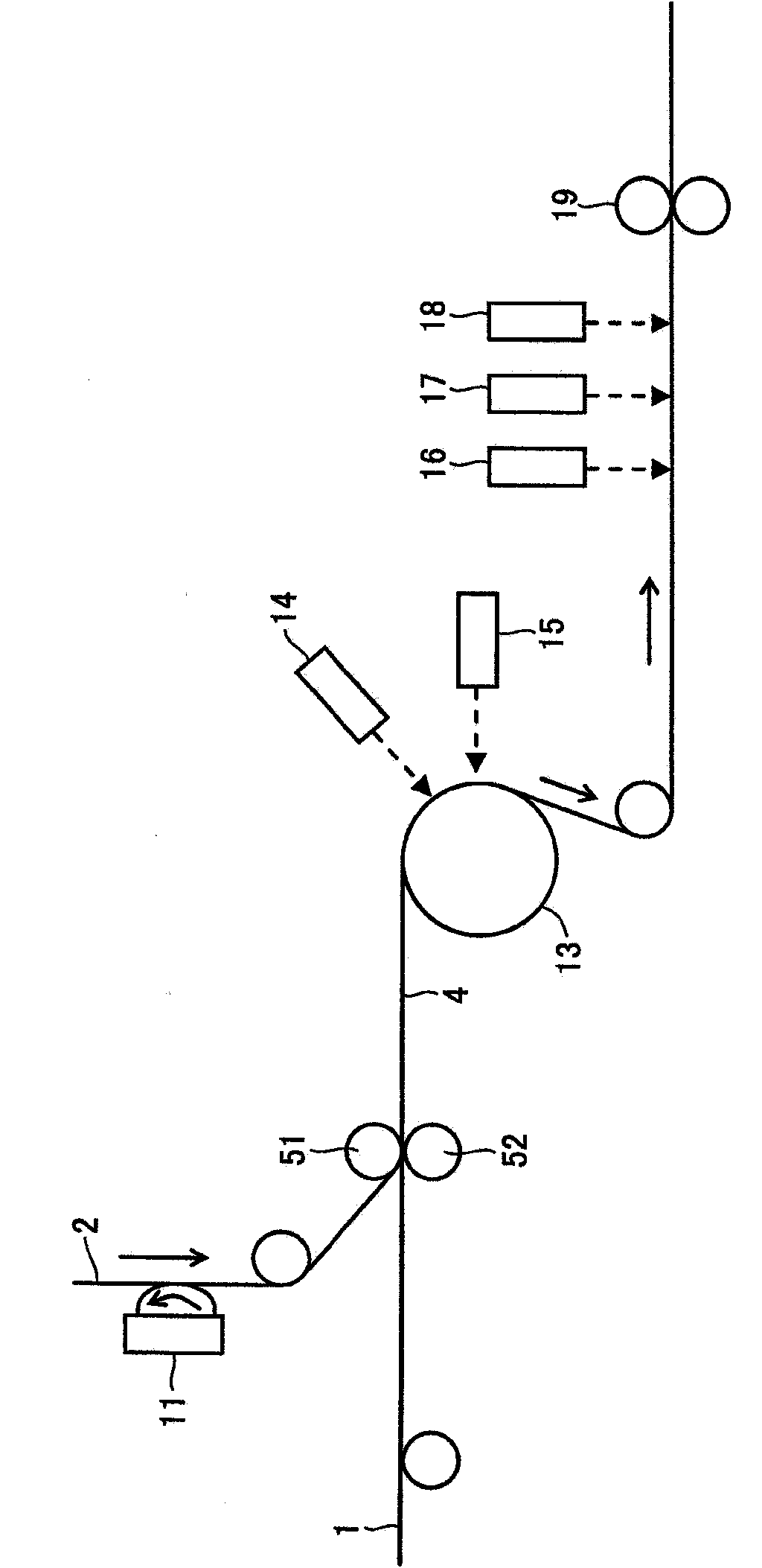
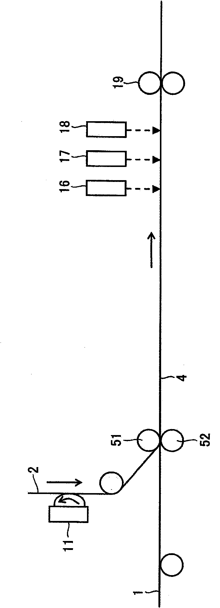
[0167] In this embodiment, the laminated film is produced from one optical film and one transparent film. In addition, in the adhesive coating step, the adhesive is coated on one side of the transparent film, and in the laminating step, the adhesive on the transparent film and one side of the optical film are In the state laminated|stacked so that contact, the said optical film and the said transparent film are pinched between the said pair of bonding rolls, and are mutually bonded.
[0168] Next, the manufacturing method of the present embodiment will be described with reference to the drawings. figure 2 It is a schematic diagram showing the structure of the whole apparatus used in the manufacturing method of this embodiment.
[0169] figure 2 In the manufacturing device of the laminated film shown in , an adhesive coating device 11 for coating an adhesive on one side of the transparent film 2 is provided sequentially along the conveying direction, and an adhesive coating...
Embodiment 1
[0176] In this example, using the above described in Embodiment 2 such as figure 2 The apparatus shown produces a laminated film in which two films are bonded together.
[0177] A 60-micrometer-thick cycloolefin resin film "ZEONOR" (manufactured by Nippon Zeon Co., Ltd.) and a 80-micrometer-thick triacetylcellulose film "KC8UX2MW" (manufactured by Konica Minolta) were prepared. The surface roughness (Rz) of the cycloolefin-based resin film was measured using "HANDYSURF (Handy Surf) E35A" manufactured by Tokyo Seiki Co., Ltd., and it was 30 nm. In addition, this value is the average value at the time of setting the measurement distance to 12.5 mm and measuring the surface roughness 10 times by mounting the said measuring apparatus on the object film.
[0178] An epoxy resin composition "KR-70T" (manufactured by ADEKA Corporation, viscosity: 44 mPa·s) as an ultraviolet-curable adhesive was applied to one side of the triacetyl cellulose film using an adhesive coating device. A...
PUM
| Property | Measurement | Unit |
|---|---|---|
| surface roughness | aaaaa | aaaaa |
| thickness | aaaaa | aaaaa |
| surface roughness | aaaaa | aaaaa |
Abstract
Description
Claims
Application Information
 - R&D
- Intellectual Property
- Life Sciences
- Materials
- Tech Scout
- Unparalleled Data Quality
- Higher Quality Content
- 60% Fewer Hallucinations
Browse by: Latest US Patents, China's latest patents, Technical Efficacy Thesaurus, Application Domain, Technology Topic, Popular Technical Reports.
© 2025 PatSnap. All rights reserved.Legal|Privacy policy|Modern Slavery Act Transparency Statement|Sitemap|About US| Contact US: help@patsnap.com


