Supercharge Your Innovation With Domain-Expert AI Agents!

Swirler

A vortex device and vortex chamber technology, applied in the field of vortex devices, can solve the problems of high noise, inability to separate oil fume, dust particle pollution, etc., and achieve the effect of reducing construction cost and operating cost, improving equipment operating efficiency, and realizing chemical reaction.

Inactive Publication Date: 2015-01-14
陈久斌
View PDF0 Cites 1 Cited by
  • Summary
  • Abstract
  • Description
  • Claims
  • Application Information

AI Technical Summary

Problems solved by technology

[0003] The existing air purification equipment has a general purification effect and cannot thoroughly treat dust, carbon dioxide, nitrogen oxides, and sulfur oxides
Existing dust removal equipment includes cyclone dust removal, electric dust removal, bag dust removal, etc., which generally have defects such as unsatisfactory dust removal effect and high energy consumption. Dust pollution has become the most important source of pollution
[0004] Existing vacuuming equipment has unsatisfactory vacuuming effect, high noise, and dust particle pollution. It is troublesome to deal with dust after dust removal
[0005] The existing range hoods cannot separate the fumes, which makes it troublesome to clean the range hoods and pollutes the environment with the fume particles. The fume particles have become another important source of urban air pollution.
[0006] The existing equipment for removing black smoke and odor has a general purification effect, and there is basically no ideal treatment method for black smoke and many chemical odors. Black smoke and odor gas pollution have become important sources of pollution
[0007] Existing oil and gas recovery equipment is too expensive, consumes too much energy, and the recovery effect is average

Method used


Image

  • Swirler
  • Swirler
  • Swirler

Examples


Embodiment Construction

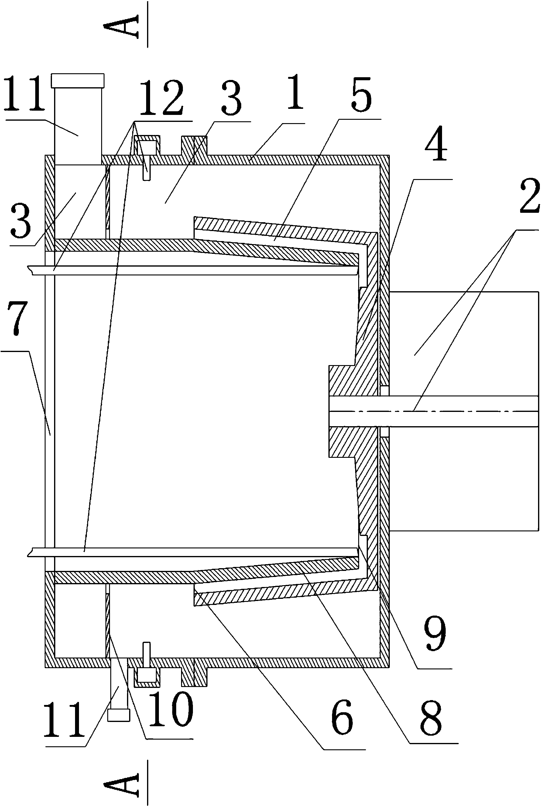
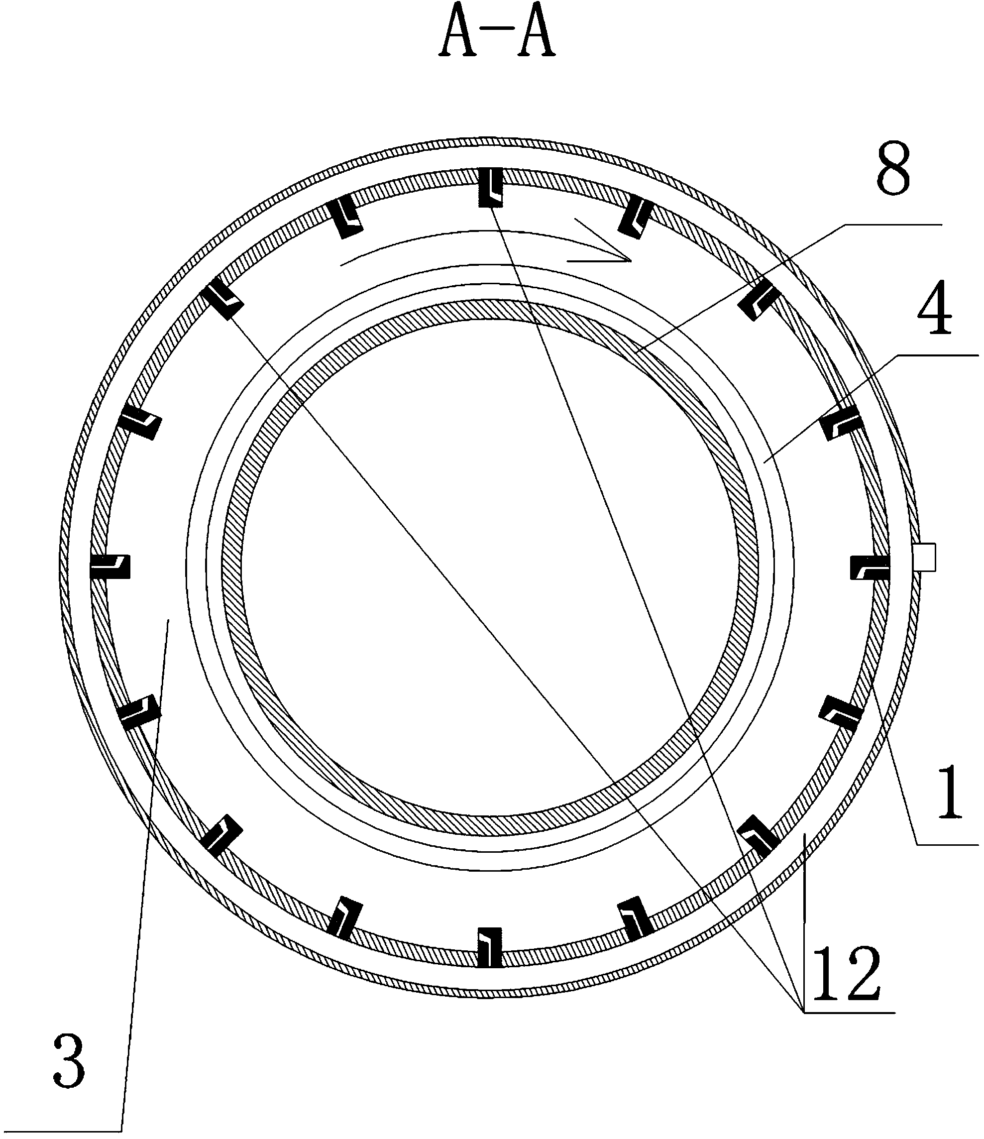
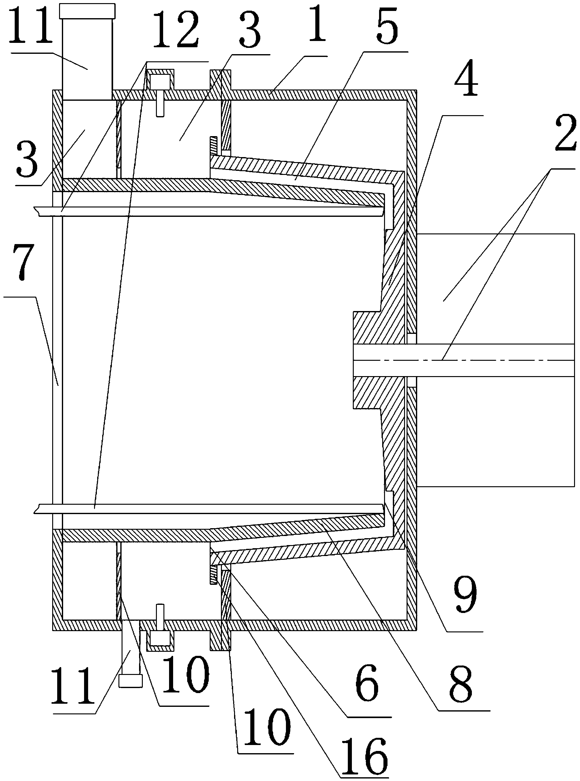
[0040] The main structure of the vortex generator of the present invention includes a housing 1 and a transmission device 2, the transmission device 2 is arranged on the housing 1, the housing chamber 3 is arranged in the housing 1, the vortex wheel 4 is arranged in the housing chamber 3, the transmission device 2 and the vortex wheel 4 connection, the vortex wheel 4 is provided with a vortex chamber 5, one end of the vortex chamber 5 is provided with a vortex chamber outlet 6, and the housing 1 is provided with a housing cavity inlet 7 corresponding to the vortex chamber outlet 6, and the housing cavity inlet 7 is connected to a guide tube 8, and the guide tube 8 penetrates into the vortex chamber 5 through the outlet 6 of the vortex chamber, the outlet 9 of the guide tube penetrates into the vortex chamber 5, at least one surrounding partition 10 is arranged on the inner wall of the casing cavity 3, and at least two discharge ports 11 are arranged on the casing cavity 3 A liq...


PUM


Abstract

The utility model discloses a swirler, which comprises a shell and a transmission device, wherein the transmission device is arranged on the shell; the shell is internally provided with a shell cavity; a swirl wheel is arranged in the shell cavity; the swirl wheel and the transmission device are connected; a swirl chamber is arranged in the swirl wheel; one end of the swirl chamber is provided with a swirl chamber outlet; a shell cavity inlet is formed, corresponding to the swirl chamber outlet, in the shell; the shell is provided with a division pipe; the shell cavity inlet is communicated with the division pipe; the division pipe passes through the swirl chamber outlet to penetrate into the swirl chamber; a division pipe outlet stretches into the swirl chamber; a circular division body is at least arranged on the inner wall of the shell cavity; the shell cavity is at least provided with two discharge holes; the shell is provided with a liquid supply device in a way of corresponding to the shell cavity. The swirler can be applied to the fields of air purification, dusting, vacuuming, desulphurization, denitration, black smoke removal, odor removal and the like, and can solve the problem of air pollution.

Description

technical field [0001] The invention relates to the fields of air purification equipment, dust removal equipment, dust suction equipment, desulfurization equipment, denitrification equipment, range hoods, chemical equipment, tail gas treatment equipment, black smoke removal, odor removal equipment, oil gas recovery equipment, etc., specifically a vortex device. Background technique [0002] Today's environmental pollution mainly includes air pollution, which has seriously affected the earth's ecological circle. [0003] The existing air purification equipment has a mediocre purification effect and cannot thoroughly treat dust, carbon dioxide, nitrogen oxides, and sulfur oxides. Existing dust removal equipment includes cyclone dust removal, electric dust removal, bag dust removal, etc., which generally have defects such as unsatisfactory dust removal effect and high energy consumption. Dust pollution has become the most important source of pollution. [0004] The existing d...

Claims


Application Information

Patent Timeline
IPC IPC(8): B04B5/00
Inventor 陈久斌
Owner 陈久斌
Features
  • R&D
  • Intellectual Property
  • Life Sciences
  • Materials
  • Tech Scout
  • Unparalleled Data Quality
  • Higher Quality Content
  • 60% Fewer Hallucinations
Learn More