Vehicle power transmission system and vehicle comprising same

A technology for a power transmission system and a vehicle is applied in the field of the power transmission system and the vehicle having the same, which can solve the problems of complex structure of the power transmission system, complicated control strategy, low transmission efficiency, etc., and achieves cost reduction, compact structure, and improved transmission efficiency. Effect

Active Publication Date: 2015-01-14
BYD CO LTD
View PDF6 Cites 19 Cited by
  • Summary
  • Abstract
  • Description
  • Claims
  • Application Information

AI Technical Summary

Problems solved by technology

[0003] However, in the related technologies known to the inventor, the power transmission system in a hybrid e

Method used


Image

  • Vehicle power transmission system and vehicle comprising same
  • Vehicle power transmission system and vehicle comprising same
  • Vehicle power transmission system and vehicle comprising same

Examples


Embodiment 1

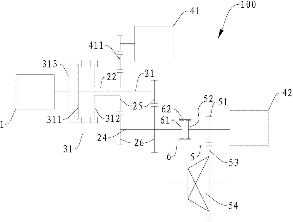
[0100] like figure 2 As shown, the engine unit 1 is connected to the input end 313 of the double clutch 31, the first output end 311 of the double clutch 31 is connected to the first input shaft 21, and the second output end 312 of the double clutch 31 is connected to the second input shaft 22, The second input shaft 22 is coaxially sleeved on the first input shaft 21 .

[0101] A driving gear 25 is fixedly arranged on the first input shaft 21 and the second input shaft 22 respectively, and the first motor generator 41 is indirectly driven with the driving gear 25 on the second input shaft 22 through an intermediate gear 411 . Two driven gears 26 are fixedly arranged on the output shaft 24 , and the two driven gears 26 respectively mesh with the driving gears 25 on the first input shaft 21 and the second input shaft 22 to form two transmission gears.

[0102] The synchronizer 6 is arranged on the output shaft 24, and the driving gear of the main reducer (that is, the output ...

Embodiment 2

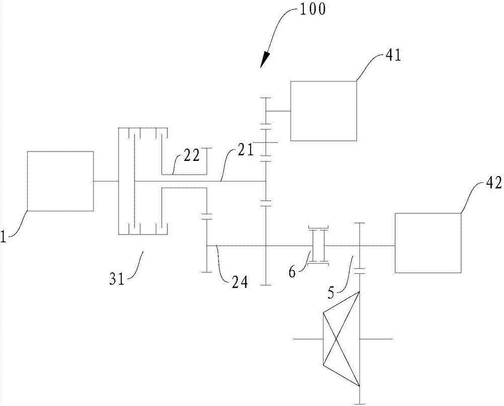
[0124] like image 3 As shown, the power transmission system 100 in this embodiment and figure 2 The difference in the power transmission system 100 may only lie in the arrangement position of the first motor generator 41 . In this embodiment, the first motor-generator 41 is indirectly driven by an intermediate gear 411 and the driving gear 25 on the first input shaft 21, and the remaining parts can be connected with figure 2 The power transmission system 100 in the embodiment is basically the same, and will not be repeated here.

Embodiment 3

[0126] like Figure 4 As shown, the power transmission system 100 in this embodiment and figure 2 The difference in the power transmission system 100 may only lie in the arrangement position of the first motor generator 41 . In this embodiment, the first motor-generator 41 is directly connected with the first input shaft 21, and when the first motor-generator 41 is generating electricity, its mechanical energy can be passed by the engine unit 1 through the dual clutch 31, the first input shaft 21 and then directly output to the first motor generator 41 for power generation. When the first motor generator 41 is used as a motor to output power, the power generated by it can be directly output to the first input shaft 21 , and then transmitted to the output shaft 24 by the first input shaft 21 through the gear set. For the rest it can be used with figure 2 The power transmission system 100 in the embodiment is basically the same, and will not be repeated here.


PUM


Abstract

The invention discloses a vehicle power transmission system and a vehicle comprising the same. The power transmission system comprises an engine unit, a transmission unit, a first electric motor generator, an output portion and a synchronizer; the transmission unit is suitable for being in dynamic coupling connection selectively with the engine unit; the first electric motor generator is in dynamic coupling connection with the transmission unit; the output portion is suitable for outputting power from the transmission unit; the synchronizer is arranged to be suitable for selective synchronization between the output portion and the transmission unit to output power through the output portion so as to drive wheels of the vehicle. According to the power transmission system of the embodiment of the invention, power output from the engine unit and/or the first electric motor generator can be output from the output portion due to the synchronization function of the synchronizer and the integral power transmission system is compact in structure and convenient to control.

Description

technical field [0001] The invention relates to the technical field of vehicles, in particular to a power transmission system for a vehicle and a vehicle with the same. Background technique [0002] With the continuous consumption of energy, the development and utilization of new energy vehicles has gradually become a trend. As one of the new energy vehicles, a hybrid vehicle is driven by an engine and / or an electric motor, and has multiple modes, which can improve transmission efficiency and fuel economy. [0003] However, in the related technologies known to the inventor, the power transmission system in a hybrid electric vehicle is generally complex in structure, bulky, and low in transmission efficiency. Strategies are complex. Contents of the invention [0004] The present invention aims to solve one of the above-mentioned technical problems in the prior art at least to a certain extent. [0005] Therefore, the present invention needs to provide a power transmissio...

Claims


Application Information

Patent Timeline
IPC IPC(8): B60K6/36B60K6/38
Inventor 杨冬生廉玉波张金涛罗红斌
Owner BYD CO LTD
Why Eureka
Try Eureka