Bus-bar middle joint for rigid suspension catenary

A technology of intermediate joints and busbars, applied in the field of intermediate joints of busbars for rigid suspension catenary, can solve the problems of different thermal expansion and contraction, safety threats of traction power supply system, loose parts of suspension system, etc., and achieves high connection strength. , The connection is reliable, and the effect of improving the tightening force

Inactive Publication Date: 2015-01-14
中铁建电气化局集团轨道交通器材有限公司
View PDF5 Cites 2 Cited by
  • Summary
  • Abstract
  • Description
  • Claims
  • Application Information

AI Technical Summary

Problems solved by technology

[0004] The segmented bus bar holds the contact line, and the cross-sectional shape of the bus bar is as attached figure 1 , has clamping walls on both sides, and the lower part has a clamp for clamping the contact wire. The intermediate joint connecting the segmented busbar is the most prone to laxity in the whole system. The main body of the intermediate joint is a pair of connecting two busbars. The threaded splint, two threaded splints are located in the clamping walls on both sides to connect the two busbars through bolts, and the bolts pass through the holes on the clamping wall and are screwed into the threaded through holes of the threaded splint. Since the bolts are steel parts, and The threaded splint is a conductive aluminum part, the hardness of the two is different, and the thermal expansion and contraction are different. During the process of digesting the influence of the pantograph at the busbar connection, the thread connection form of the intermediate joint will slip, resulting in the entire suspension system being zero. Components are loose, which poses a great threat to the safety of the traction power supply system

Method used


Image

  • Bus-bar middle joint for rigid suspension catenary
  • Bus-bar middle joint for rigid suspension catenary
  • Bus-bar middle joint for rigid suspension catenary

Examples


Embodiment Construction

[0019] The present invention is described in further detail now in conjunction with accompanying drawing.

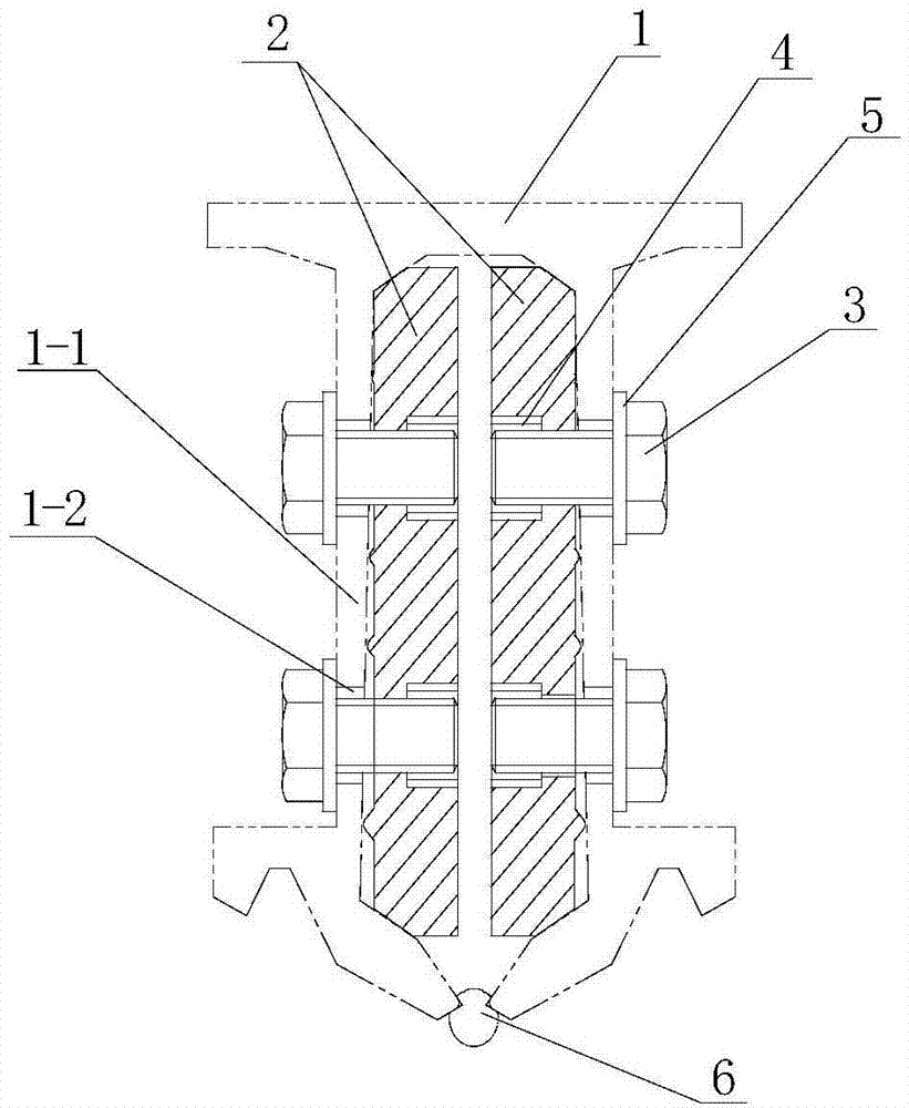
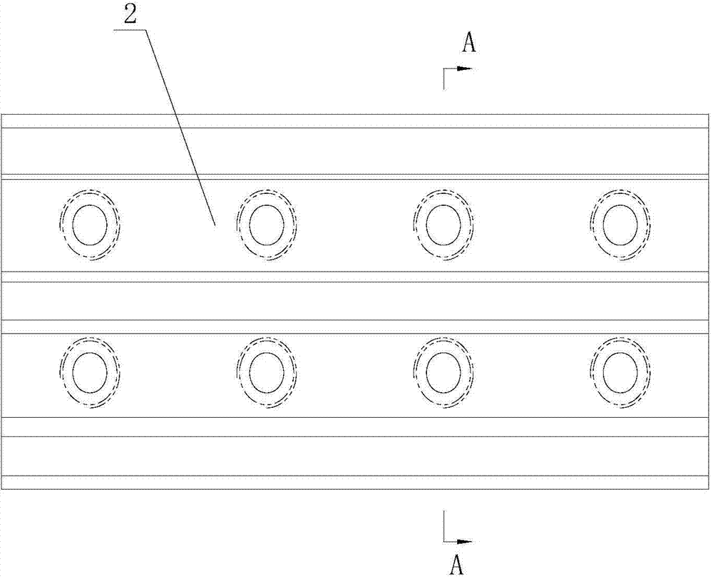
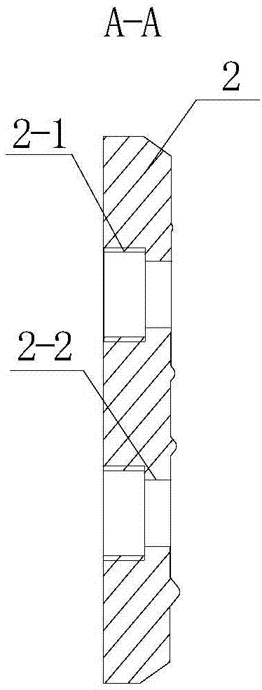
[0020] A kind of busbar intermediate joint for rigid suspension catenary, as attached figure 1 , has a pair of threaded splints 2 that are arranged on both sides of the busbar 1 in the clamping walls 1-1 to connect two busbars 1, and pass through the holes 1-2 on the busbar 1 to connect the two ends of the threaded splint 2 to the two busbars respectively. row 1 fixed bolt 3, as attached figure 2 , 3 , the mounting hole on the threaded splint 2 has a constricted light hole section 2-2 at the mouth and a threaded section 2-1 at the bottom, attached figure 2 The specific method is that there are 8 mounting holes, and then there are 4 holes 1-2 at the end of the connected bus bar 1.

[0021] The intermediate joint also has a steel threaded sleeve 4 that is threaded both inside and outside the ring, as attached Figure 4 , 5 , the external thread of the threaded sleev...


PUM


Abstract

The invention relates to the technical field of a high-speed electric railway catenary, in particular to a bus-bar middle joint for a rigid suspension catenary, and solves the problem that looseness can be easily generated among the existing catenary bus-bars under the frequent impact condition. The bus-bar middle joint has the scheme that the middle joint is provided with a pair of threaded clamp plates and screw bolts, the clamp plates are respectively arranged in clamp walls at two sides of the bus-bars and are internally connected with two bus-bars, the screw bolts pass through holes formed in the bus-bars and are used for fixing the two ends of the threaded clamp plates with the two bus-bars, an installing hole formed in each threaded clamp plate is provided with a contractive unthreaded hole section positioned at the opening part and a threaded section positioned at the bottom, the middle joint is also provided with an annular steel threaded sleeve provided with screw threads at inside and outside, the external screw threads of the threaded sleeve are suitable for the threaded section of the corresponding threaded clamp plate to be screwed in, the internal screw threads of the threaded sleeve are suitable for the screw bolts to be screwed in, the inner diameter of the contractive unthreaded hole section arranged on the each threaded clamp plate is greater than that the screw diameter of each screw bolt, and the middle joint is also provided with flat pads which sheath the screw bolts and are positioned outside the bus-bar holes.

Description

technical field [0001] The invention relates to the technical field of high-speed electrified railway catenary, in particular to a bus bar intermediate joint for rigid suspension catenary. Background technique [0002] In recent years, with the rapid development of social economy, higher requirements have been put forward for railway transportation. In order to adapt to the continuous speed increase of railways under the new situation, higher requirements have been put forward for the technical requirements of catenary components. [0003] With the increase of the operation time and the higher and higher traffic density, the contact pressure and impact pressure of the pantograph will superimpose energy during the reciprocating driving process, which will affect the rigid suspension without lifting amount, which needs to be digested by the entire catenary system . [0004] The segmented bus bar holds the contact line, and the cross-sectional shape of the bus bar is as attach...

Claims


Application Information

Patent Timeline
Patent Type & Authority Applications(China)
IPC IPC(8): B60M1/24
Inventor 陆佳张亮张敏王旭李东升
Owner 中铁建电气化局集团轨道交通器材有限公司
Why Eureka
Try Eureka