High-temperature-resistant electric control hoisting electro permanent magnet

A permanent magnet and high temperature resistant technology, applied in the direction of load hanging components, transportation and packaging, etc., can solve the problems of insufficient electromagnet suction, falling of the attracted object, limitation of permanent magnet steel Curie point, etc., and achieve insulation performance and durability Excellent thermal performance, good moisture resistance, low temperature coefficient effect

Inactive Publication Date: 2015-01-14
马鞍山起劲磁塑科技有限公司
View PDF6 Cites 7 Cited by
  • Summary
  • Abstract
  • Description
  • Claims
  • Application Information

AI Technical Summary

Problems solved by technology

[0002] At present, the lifting electromagnet is a special electromagnet that uses the attracted object as the armature. It uses the magnetic field generated after the coil is energized to absorb the attracted object. It must always be energized during the lifting process. If the cable is broken , the power failure protection system cannot supply power to the electromagnet, and there will be accidents where the electromagnet loses its magnetic field and the attracted object falls
When lifting high-temperature and ultra-high-temperature billets, the conventional electromagnet often has insufficient suction and the billet falls off. The main reason is that the electromagnet itself generates heat, and the heat cannot be dissipated. Conventional products, for products at 300°C and above, are limited by the Curie point of permanent magnet steel and cannot be used at high temperatures

Method used


Image

  • High-temperature-resistant electric control hoisting electro permanent magnet
  • High-temperature-resistant electric control hoisting electro permanent magnet
  • High-temperature-resistant electric control hoisting electro permanent magnet

Examples


Embodiment Construction

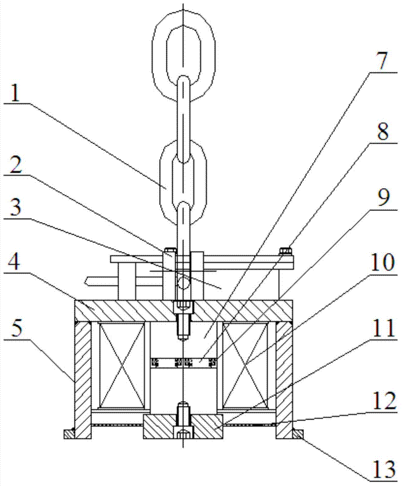
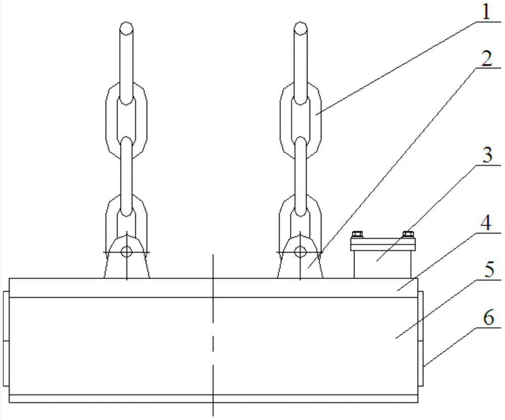
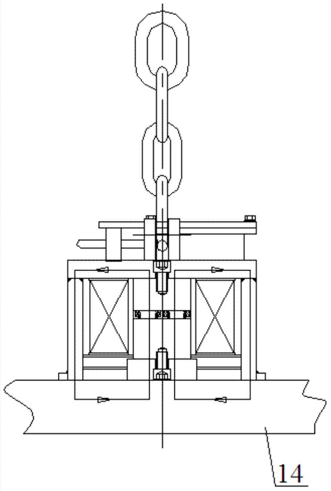
[0021] Referring to the accompanying drawings, a high-temperature-resistant electronically controlled lifting electro-permanent magnet includes a chain 1 connected to a hoisting device, a lifting lug 2 arranged at the bottom of the chain 1 and an electro-permanent magnet fixedly connected to the bottom of the lifting lug 2, the electro-permanent The magnet is a sealed overall structure consisting of top plate 4, side plate 5, end plate 6, inner magnetic plate 11 and heat insulation plate 12. An iron core 7 is arranged in the middle of the inside of the electro-permanent magnet, and the outer cover of the iron core 7 is provided with a main The excitation coil 10, the middle part of the iron core 7 are respectively provided with multiple groups of magnetic steel 8, the multiple groups of magnetic steel 8 are respectively covered with degaussing coils 9, and the bottom end of the electro-permanent magnet is provided with an outer magnetic pole 13;

[0022] The top plate 4, the si...


PUM


Abstract

The invention discloses a high-temperature-resistant electric control hoisting electro permanent magnet which comprises chains connected with hoisting equipment, lifting lugs arranged at the bottom ends of the chains, and an electro permanent magnet body fixedly connected to the bottom ends of the lifting lugs, wherein the electro permanent magnet body is of a sealed integrated structure consisting of a top plate, side plates, an end plate, an inner magnetic plate and a heat insulation plate; an iron core is arranged in the middle in the electro permanent magnet body; main excitation coils sleeve the outside of the iron core; a plurality of groups of magnetic steel are respectively arranged in the middle of the iron core; demagnetization coils respectively sleeve the outside of the multiple groups of magnetic steel; an outer magnetic pole is arranged at the bottom end outside the electro permanent magnet body; the top plate, the side plates, the outer magnetic pole, the inner magnetic plate, the iron core and the multiple groups of magnetic steel form a magnetic loop. According to the high-temperature-resistant electric control hoisting electro permanent magnet, current meeting different demands is generated by using electric control energy; during excitation, the high direct current is supplied; during demagnetization, the intermediate-frequency alternating current is supplied to the demagnetization coils; and therefore, extremely good and convenient control can be realized.

Description

technical field [0001] The invention relates to the field of equipment for lifting high-temperature billets used in industrial production, in particular to a high-temperature-resistant electric-controlled lifting permanent magnet. Background technique [0002] At present, the lifting electromagnet is a special electromagnet that uses the attracted object as the armature. It uses the magnetic field generated after the coil is energized to absorb the attracted object. It must always be energized during the lifting process. If the cable is broken , the power failure magnetic protection system cannot supply power to the electromagnet, and there will be an accident that the electromagnet loses its magnetic field and the attracted object falls. When lifting high-temperature and ultra-high-temperature billets, the conventional electromagnet often has insufficient suction and the billet falls off. The main reason is that the electromagnet itself generates heat, and the heat cann...

Claims


Application Information

Patent Timeline
Patent Type & Authority Applications(China)
IPC IPC(8): B66C1/06
CPCB66C1/06
Inventor 周国胜严云芳胡乘刚
Owner 马鞍山起劲磁塑科技有限公司
Why Eureka
Try Eureka