Supercharge Your Innovation With Domain-Expert AI Agents!

False-twisting device and process method for single-spindle disc-type ring spinning

A process method and false twisting technology, applied in the direction of textiles and papermaking, etc., can solve the problems of enlarging arc, increasing the actual length of spinning section, difficulty in threading, etc.

Inactive Publication Date: 2016-09-07
JIANGNAN UNIV
View PDF16 Cites 1 Cited by
  • Summary
  • Abstract
  • Description
  • Claims
  • Application Information

AI Technical Summary

Problems solved by technology

In the spinning-in process of the above-mentioned devices, the yarn needs to pass through the hole of an additional false twister, which makes spinning-up extremely difficult
In the above-mentioned patent, when installed on the existing spinning equipment, the spatial position and spatial state of the existing spinning section will be changed, causing the encircling arc between the yarn and the front roller to increase, or changing the distance between the yarn and the yarn guide hook. The change of these parameters increases the actual length of the spinning section, which affects the application of the existing mature spinning process theory

Method used


Image

  • False-twisting device and process method for single-spindle disc-type ring spinning
  • False-twisting device and process method for single-spindle disc-type ring spinning

Examples


Embodiment approach 1

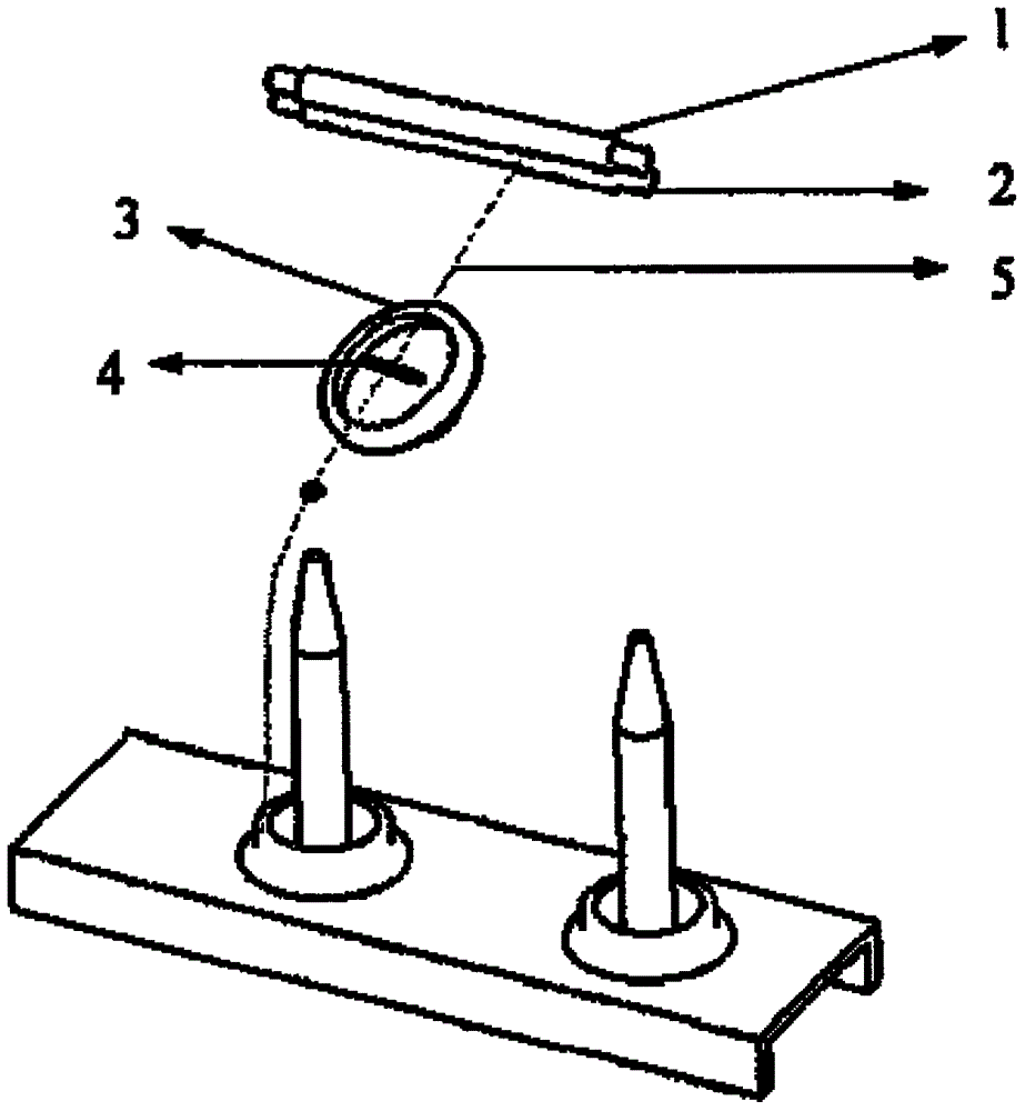
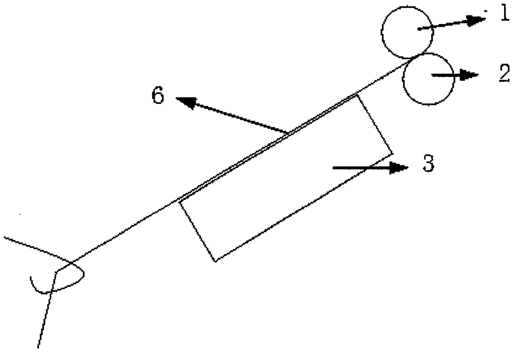
[0026] figure 1 and figure 2 They are the three-dimensional schematic diagram of the spinning device, and the geometric relationship diagram between the spinning section and the false twist disc. Such as figure 1 , 2 As shown, the fiber bundle 5 output by the front nip of the drafting system composed of the front roller 2 and the front rubber roller 1 passes through the upper side of the false twisting disc 3, and then under the action of the separation rod 4, the false twisting disc 3 The spinning section is closely combined with the upper side and the lower side of the false twisting disc 3, and the false twisting disc rotating at high speed performs false twisting on the spinning section.

Embodiment approach 2

[0028] figure 1 and figure 2 They are the three-dimensional schematic diagram of the spinning device, and the geometric relationship diagram between the spinning section and the false twist disc 3, respectively. Put a circular rubber ring on the false twisting disc 3, the fiber bundle 5 output by the front nip of the drafting system composed of the front roller 2 and the front rubber roller 1 passes through the upper side of the rubber ring of the false twisting disc 3, Then under the action of the spacer bar 4, the false twist disc spinning segment 6 is closely combined with the rubber ring upper and lower sides of the false twist disc 3, and the false twist disc 3 rotating at high speed performs false twisting to the spinning segment.


PUM


Abstract

The invention discloses a single-spindle disc-type ring spinning false twisting device and technique. The single-spindle disc-type ring spinning false twisting device comprises a rotary disc-type false twisting device body which is installed on a ring spinning frame and a separation rod. A spinning yarn section outputted by front rollers are falsely twisted by adopting two twisting points formed by one rotary disc, and the separation rod is installed between the two false twisting points and plays a role in separating the two false twisting points and increasing the pressure between the spinning yarn section and the selected disc. The twisting degree distribution of the spinning yarn section can be adjusted by controlling the rotation speed of the rotary disc and the output speed of a front roller yarn under the condition of determining the diameter parameter of the rotary disc; and the needed performance of a final yarn can be acquired by adjusting the oscillating angle of the separation rod and adjusting a contact angle of the yarn on the rotary disc. By adopting the single-spindle disc-type ring spinning false twisting device, the size of a spinning twisting triangular area can be reduced, the twisting degree of the yarn in the spinning triangular area can be increased, the strength of fiber beams in the spinning twisting triangular area can be improved, and finally the hairiness of the final yarn can be reduced.

Description

technical field [0001] The present invention relates to spinning technology for the manufacture of ring-spun yarns. The present invention particularly relates to the following device and process method, which utilizes disc-type false-twisting equipment to perform false-twisting on the spinning section of the existing spinning frame, so as to improve the strength, hairiness, twist and other properties of the final yarn. The system has convenient operation performance. Background technique [0002] Twisted yarns have twist instabilities resulting in residual torque. This residual torque of the yarn has an impact on the processing quality of the subsequent product, making the subsequent processing process more difficult. Therefore, such residual torque should be prevented to the greatest extent possible in the spinning industry. [0003] Since the spun yarn is made of fibers through twisting, the residual torque of the yarn is mainly affected by the type of fiber, the shape ...

Claims


Application Information

Patent Timeline
Patent Type & Authority Patents(China)
IPC IPC(8): D01H7/92
CPCD01H7/923
Inventor 刘基宏刘建立陈辉张明霞朱涛涛
Owner JIANGNAN UNIV
Features
  • R&D
  • Intellectual Property
  • Life Sciences
  • Materials
  • Tech Scout
  • Unparalleled Data Quality
  • Higher Quality Content
  • 60% Fewer Hallucinations
Learn More