Pipe joint for heat exchanger

A technology for heat exchangers and pipe joints, which is applied in the field of pipe joints, can solve problems such as thermal deformation, and achieve the effects of less thermal deformation and less strength reduction

Inactive Publication Date: 2015-01-14
SHANGHAI RINNAI
View PDF4 Cites 1 Cited by
  • Summary
  • Abstract
  • Description
  • Claims
  • Application Information

AI Technical Summary

Problems solved by technology

In view of the above-mentioned defects in the prior art, the technical problem to be solved by the present invention is to provide a pipe joint that reduces subsequent manufacturing costs and simultaneously solves the problems of thermal deformation and strength reduction

Method used


Image

  • Pipe joint for heat exchanger
  • Pipe joint for heat exchanger
  • Pipe joint for heat exchanger

Examples


Embodiment Construction

[0054] The specific implementation manners of the present invention will be further described in detail below in conjunction with the accompanying drawings and embodiments. The following examples are used to illustrate a specific embodiment of the present invention, but are not intended to limit the scope of the present invention.

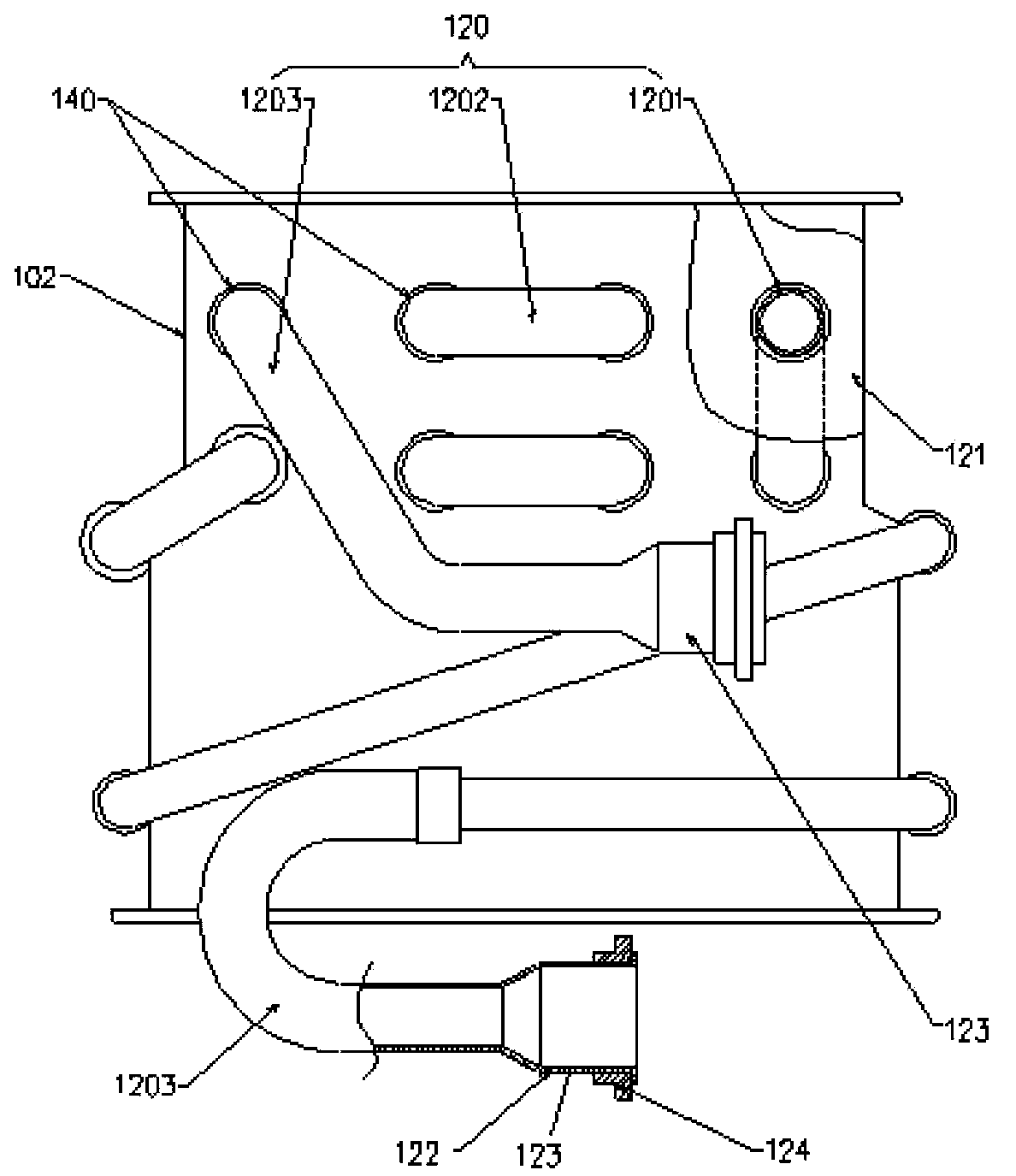
[0055] figure 1 It shows a schematic structural diagram of a water heater in the prior art. A plurality of plate-shaped heat-absorbing fins (121) are arranged side by side in the box (102), and the pipe (120) flowing with the heated fluid inside goes back and forth multiple times and runs through the box. Body and plate-shaped heat-absorbing fins (121), the pipe (120) is composed of three parts, namely the straight pipe part (1201), the U pipe part (1202) and the connecting pipe part (1203), and the straight pipe part is stored in the box Inside the body (102), the U pipe part is a U-shaped pipe connected to the adjacent straight pipe parts (1201)...


PUM


Abstract

The invention discloses a heat exchanger which is provided with a heat-proof copper pipe joint. The pipe joint comprises a pipe which is made of copper and a pipe joint which is made of heat-proof copper; the pipe which is accommodated inside a box body penetrates the box body to extend; the pipe joint is formed by stamping; one end of the pipe joint is connected with the end portion of the copper pipe which penetrates the box body to extend; the other end of the pipe joint is connected with the connecting end portion of an external matching pipe. The heat exchanger is formed by brazing of the box body, the pipe and the pipe joint at welding object positions inside a furnace, working procedures of the heat exchanger are reduced, and the production efficiency is improved. The invention also provides a manufacturing method of the heat exchanger based on the pipe joint.

Description

technical field [0001] The invention relates to the technical field of pipe joints, in particular to a pipe joint for heat exchangers. Background technique [0002] Heat exchangers such as water heaters need to use pipe joints when connecting pipes. For example, a heat exchanger is provided with a tube that is housed in a box and extends through the box, and a pipe joint is required to connect the tube to an external pipe. Pipe joints are generally made by cutting brass materials. When a pipe joint of this material is used, if the pipe joint and the joint end of the pipe are combined and welded in a furnace, the change in the material of the pipe joint will cause problems such as insufficient strength of the port, rough surface, and poor appearance. Therefore, when using this kind of pipe joint, the method of manual brazing of the pipe joint and the pipe is generally adopted, which brings a series of problems such as complicated manufacturing process, long time required fo...

Claims


Application Information

Patent Timeline
IPC IPC(8): F28F9/26F16L25/10
Inventor 进士克彦徐蔚春章凯
Owner SHANGHAI RINNAI
Why Eureka
Try Eureka