Counterforce beam loading device and loading method for static load test of bridge beam body

A loading device and reverse force loading technology, which is applied in the direction of applying stable tension/pressure to test the strength of materials, can solve the problems that the loading position of the static load test is not easy to change, the loading position is not easy to move, and the strain data is easy to drift, etc., to achieve saving Test cost, easy processing and disassembly, and good loading effect

Inactive Publication Date: 2015-01-14
TONGJI UNIV
View PDF4 Cites 14 Cited by
  • Summary
  • Abstract
  • Description
  • Claims
  • Application Information

AI Technical Summary

Problems solved by technology

Among them, when the heavy object accumulation loading method is used for loading, the heavy objects such as sandbags or prefabricated concrete blocks are used for loading. And it takes a long time; ②The loading process is long, the strain data is easy to drift, and the data error is large; ③When loading to the beam body failure stage, the loaded heavy objects fall, which is prone to danger, and the risk factor is high
However, when the ground anch...

Method used


Image

  • Counterforce beam loading device and loading method for static load test of bridge beam body
  • Counterforce beam loading device and loading method for static load test of bridge beam body
  • Counterforce beam loading device and loading method for static load test of bridge beam body

Examples


Embodiment Construction

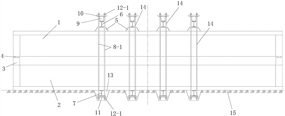
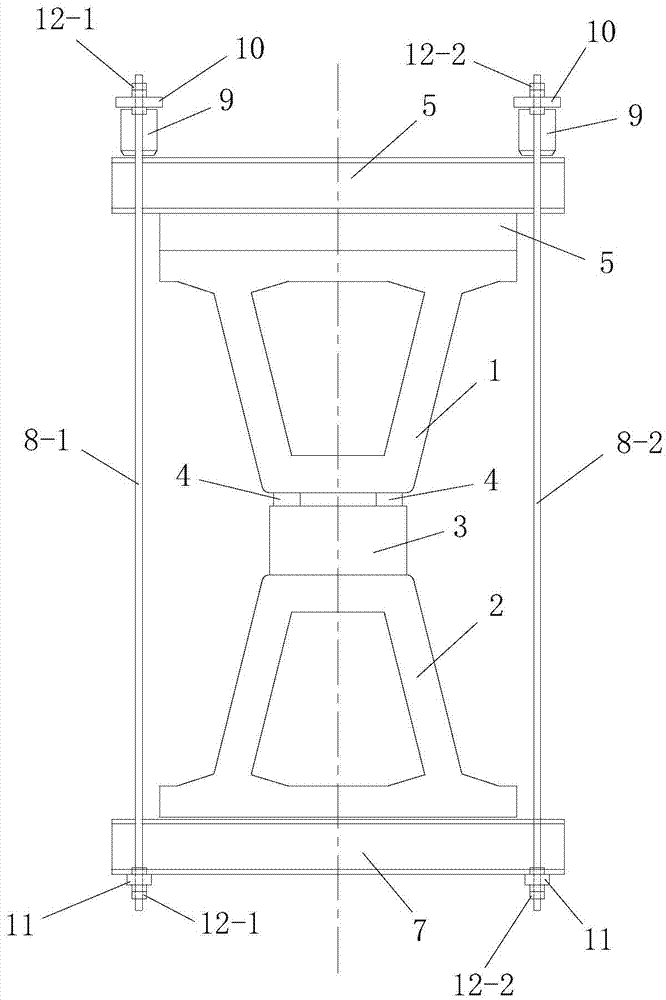
[0042] Such as figure 1 The shown a kind of bridge girder body static load test uses the reaction beam loading device, comprises the reaction force loading beam 2 that is positioned at the test beam 1 directly below and the loading mechanism 14 that is installed on the test beam 1, and the described test beam 1 is to carry out static load Tested bridge girder. The loading mechanism 14 is located at the position where the test beam 1 needs to be loaded, and the number of the loading mechanism 14 is one or more, and the multiple loading mechanisms 14 are arranged along the longitudinal direction of the test beam 1 from front to back. The reaction loading beam 2 is a beam body with the same structure and size as the test beam 1, and the reaction loading beam 2 and the test beam 1 are arranged symmetrically up and down, and the two ends of the test beam 1 and the reaction loading beam 2 There are beam end support pads 3 between the support pads. Both the test beam 1 and the reac...


PUM


Abstract

The invention discloses a counterforce beam loading device for a static load test of a bridge beam body. The counterforce beam loading device comprises a counterforce loading beam which is arranged right below a test beam and a loading mechanism which is installed on the test beam, wherein the counterforce loading beam and the test beam are symmetrically arranged in the vertical direction, and a beam-end supporting cushion block is arranged between the counterforce loading beam and the test beam in a lining manner; the loading mechanism comprises an upper crossbeam, a lower crossbeam, a pressurizing mechanism, an upper ejector plate and a lower liner plate, and the upper ejector plate and the lower liner plate are connected with each other through a drawing bar. The loading device adopts a beam body which is the same as the test beam as the counterforce loading beam and has advantages of simple structure, low cost, good loading effect, simplicity in loading position adjustment, safety in loading and the like. Meanwhile, the invention also discloses a counterforce beam loading method. The method comprises the following steps of I, leveling a test field; II, hoisting the counterforce loading beam in place; III, arranging the beam-end supporting cushion block; IV, hoisting the test beam in place; V, installing the loading mechanism; and VI, loading. The method is simple in step, convenient to realize, low in investment cost, short in loading time, good in loading effect and wide in application range.

Description

technical field [0001] The invention belongs to the technical field of bridge static load tests, and in particular relates to a reaction beam loading device and a loading method for static load tests of bridge girder bodies. Background technique [0002] In the process of studying the bridge structure, the method of loading test is often used to observe the crack development, deflection, strain and other data of the bridge beam body and the failure mode under the condition of gradual loading. The bridge beam static load test is a widely used beam loading test method at present. Static load test of bridge beam body, also known as static load test, refers to applying static load to a designated position on the bridge beam body, and observing the static displacement, static strain, crack, settlement and other parameters of the bridge structure (specifically, the beam body) test top. Among them, the static load refers to the load that does not change with time, such as the sel...

Claims


Application Information

Patent Timeline
IPC IPC(8): G01N3/12
Inventor 蒲广宁肖汝诚张晓栋程进
Owner TONGJI UNIV
Why Eureka
Try Eureka