Electric steering engine electrical failure rapid detection circuit and method

An electric steering gear and detection circuit technology, applied in the detection field, can solve problems such as circuit and component damage

Active Publication Date: 2015-01-14
LANZHOU FLIGHT CONTROL
View PDF1 Cites 3 Cited by
  • Summary
  • Abstract
  • Description
  • Claims
  • Application Information

AI Technical Summary

Problems solved by technology

[0003] The purpose of the present invention is: to propose a kind of electric steering gear electric failure rapid detection circuit and its detection method, so that before the steering gear is energized to work, detect whether the electric steerin

Method used


Image

  • Electric steering engine electrical failure rapid detection circuit and method
  • Electric steering engine electrical failure rapid detection circuit and method

Examples


Embodiment 1

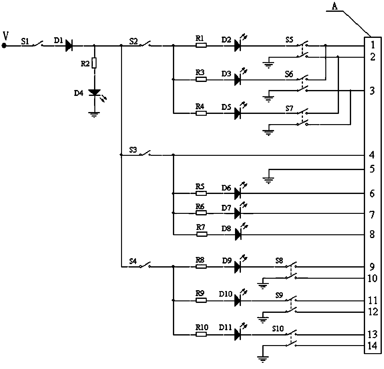
[0089] In Embodiment 1 of the present invention, the stator winding of the motor in the electric steering gear is detected, and the detection preparation is made according to the detection step 1, and then the first SPST switch S1 and the second SPST switch S2 are closed. Double-pole single-throw switch S5, the state of the first double-pole single-throw switch S5 and the first light-emitting diode D2 is recorded in the stator winding detection truth table, and its values ​​are: S5 is 1, S6 is 0, S7 is 0, D2 is 0; when the second double-pole single-throw switch S6 is closed, the state of the first double-pole single-throw switch S5 and the first light-emitting diode D2 is recorded in the stator winding detection truth table, and its value is: S5 is 1, S6 is 0, S7 is 0, D2 is 0; then the first double-pole single-throw switch S5 is disconnected; the second double-pole single-throw switch S6 is closed, and the second double-pole single-throw switch S6 and the second light-emitting...

Embodiment 2

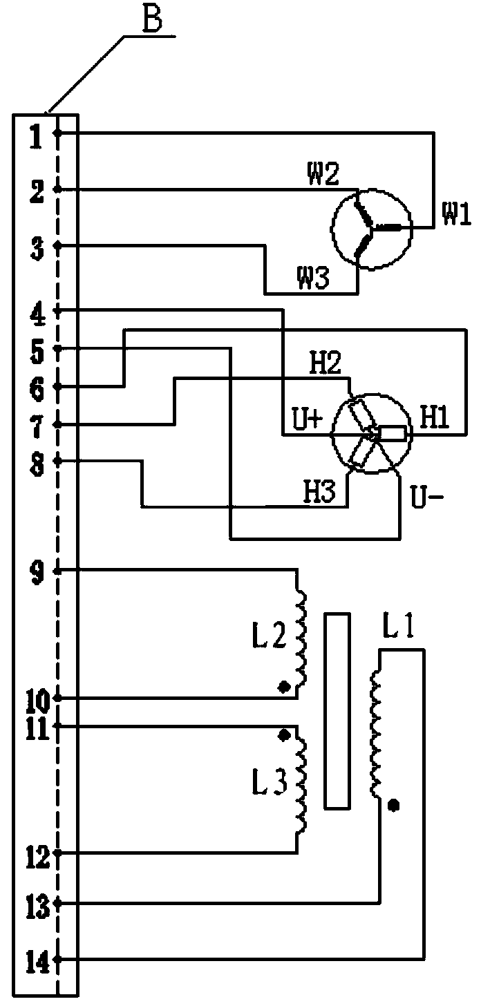
[0091] In Embodiment 2 of the present invention, the motor Hall commutation unit in the electric steering gear is detected, and the detection preparation is made according to the detection step 1,

[0092] Then close the third single-pole single-throw switch S3, continuously rotate the rotating shaft of the electric steering gear in one direction by hand, and observe the on-off status of the fifth light-emitting diode D6, the sixth light-emitting diode D7, and the seventh light-emitting diode D8; The fifth light-emitting diode D6 and the seventh light-emitting diode D8 are turned on and then turned off, and the sixth light-emitting diode D7 is always off, so it can be judged that the H2 phase of the brushless DC motor Hall commutation unit in the steering gear exists Fault; After completing the detection of the motor Hall commutation unit of the electric steering gear, disconnect the third single-pole single-throw switch S3;

Embodiment 3

[0094]In embodiment 3 of the present invention, the position sensor of the electric steering gear is detected, and the detection preparation is made according to the detection step 1, and then the fourth single-pole single-throw switch S4 is closed, the fourth double-pole single-throw switch S8 is closed, and the eighth light-emitting diode If it is on, it is judged that the secondary winding L2 of the position sensor is not faulty; when the fifth double-pole single-throw switch S9 is closed, the ninth light-emitting diode D10 is lit, and it is judged that the secondary winding L3 of the position sensor is faultless; when the sixth double-pole single-throw switch S10 is closed , the tenth light-emitting diode D11 does not light up, and it is determined that the secondary winding L2 of the position sensor is disconnected. After the position sensor detection of the electric steering gear is completed, the fourth SPST switch S4 is turned off.


PUM


Abstract

The invention relates to an electric steering engine electrical failure rapid detection circuit and method. The electric steering engine electrical failure rapid detection circuit is formed by a first single-pole single-throw switch S1 to a fourth single-pole single-throw switch S4, a first double-pole single-throw switch S5 to a sixth double-pole single-throw switch S10, a diode D1, a first light emitting diode D2 to a tenth light emitting diode D11, a resistor R1 to a resistor R10 and an electric connector plug (1). The electric steering engine electrical failure rapid detection method can be used for failure detection on a stator winding of a motor in an electric steering engine, a motor Hall reversing unit of the electric steering engine and a position sensor in the electric steering engine. Before the steering engine is powered on and runs, whether broken wires, staggered wires and short-circuit wires exist in the electric steering engine can be detected, damage caused by blind power-on work to related circuits and members is avoided, rapid electrical failure detection and accurate positioning of a known breakdown steering engine are achieved, the whole detection process is rapid, efficient, simple, and the detection circuit and method are high in universality.

Description

technical field [0001] The invention belongs to the detection technology, and relates to a fast detection circuit and a detection method for electric faults of an electric steering gear. Background technique [0002] At present, after the assembly of the electric steering gear is completed, during debugging and troubleshooting, whether the electrical connection is correct, whether there are disconnected wires, crossed wires, short-circuited wires, etc. in the wiring, generally only after the steering gear is energized can it be discovered and corrected. Judgment. However, judging the correctness of the electrical connection through the power-on work of the steering gear is very risky, and it is easy to cause damage to related circuits and components. For example, if the Hall signal line and power line of the steering gear are connected incorrectly, the Hall element will be burnt out. When the winding wire of the displacement sensor is disconnected, the steering gear will mo...

Claims


Application Information

Patent Timeline
IPC IPC(8): G01R31/02G01R31/06
Inventor 李建
Owner LANZHOU FLIGHT CONTROL
Why Eureka
Try Eureka