Combining-optics prism parallel connection micro-motion device for laser gyroscope combining-optics assembly

A light-combining prism and laser gyro technology, applied in installation, optics, optical components, etc., to achieve the effect of strong rigidity, good dynamic performance, and simple and compact structure

Inactive Publication Date: 2015-01-14
SHANGHAI UNIV
View PDF4 Cites 8 Cited by
  • Summary
  • Abstract
  • Description
  • Claims
  • Application Information

AI Technical Summary

Problems solved by technology

[0004] The purpose of the present invention is to provide a light-combining prism adjustment device based on a parallel micro-motion mechanism in view of the problems existing in the existing manually-operated light-combining prism adjustment process, with flexible motion output trajectory, small moment of inertia and good dynamic performance , Simple and compact structure, strong rigidity and high precision, which help to improve the quality and efficiency of laser gyroscope assembly

Method used


Image

  • Combining-optics prism parallel connection micro-motion device for laser gyroscope combining-optics assembly
  • Combining-optics prism parallel connection micro-motion device for laser gyroscope combining-optics assembly
  • Combining-optics prism parallel connection micro-motion device for laser gyroscope combining-optics assembly

Examples


Embodiment 1

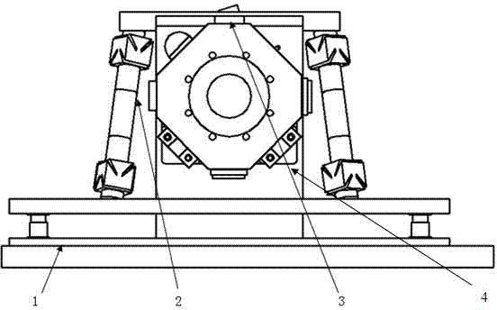
[0024] control figure 1 , 2 , 3, 4, 5, 6, 7, 8, the light-combining prism parallel micro-movement device used for laser gyro light-combining assembly, including an optical platform (1), a light-combining prism parallel micro-motion platform (2) and The optical element (3) to be assembled in the laser gyro optical combination assembly. The light-combining prism parallel micro-motion platform (2) and the optical element (3) to be assembled in the laser gyro light-combining assembly are placed in the middle of the optical platform (1), and the light-combining prism parallel micro-motion platform (2) is fixed on the optical platform (2) by screws. On the platform (1), the optical element (3) to be assembled in the laser gyro light combination assembly is connected to the optical platform (1) through an adapter plate (4); the light combination prism parallel micro-motion platform (2) has Four linear drive rods (20) drive the light-combining prism (7) in the optical element (3) to...

Embodiment 2

[0025] Embodiment 2: This embodiment is basically the same as Embodiment 1, and the special features are as follows:

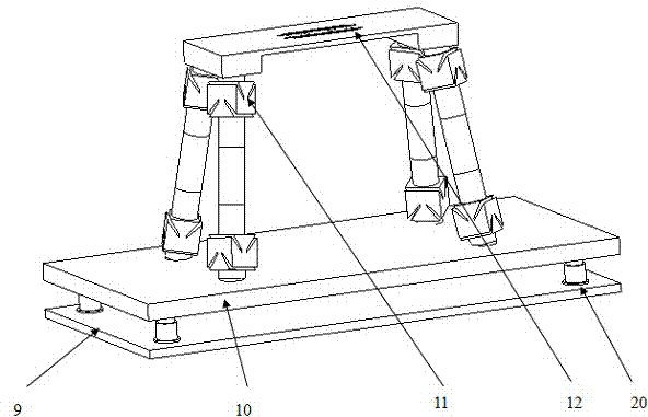
[0026] control figure 1 , 2 , 3. The light-combining prism parallel micro-motion platform (2) includes a bottom plate (9), a vertical lifting platform (10), four parallel branch chains (11) and a light-combining prism clamping mechanism (12) , the bottom plate (9) is fixed on the optical table (1), the vertical lifting platform (10) is fixed above the bottom plate (9), and one end of the parallel branch chain (11) is welded on the vertical lifting platform (10), The other end of the parallel branch chain (11) is welded to the light-combining prism clamping mechanism (12), and the four parallel branch chains (11) are symmetrically arranged between the vertical lifting platform (10) and the light-combining prism clamping mechanism (12) .

[0027] control figure 1 , 2 , 3, 4, the parallel branch chain (11) includes a first flexible Hooke hinge (13), a piezoe...

Embodiment 3

[0029] Embodiment 3: This embodiment is basically the same as Embodiment 1, and the special features are as follows:

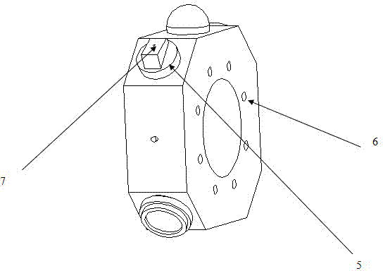
[0030] control figure 1 , 2 , the optical element (3) to be assembled in the laser gyro light combining assembly is composed of a resonant cavity (5), a plane mirror (6), and a light combining prism (7), and the plane mirror (6) is placed horizontally in the resonant cavity Body (5) laser beam exit port, light-combining prism (7) is placed horizontally on the plane mirror (6), in a free optical gel state. Through the adjustment of the mechanism, the operation of the light combining prism (7) is realized, so that the light spots of the clockwise and counterclockwise beams of light emitted overlap.

[0031] control Image 6 , the rotational movement state of the combined light prism (7) around the Z axis in space.

[0032] control Figure 7, the translational motion state of the light-combining prism (7) along the X-axis in space.

[0033] control Figure...


PUM


Abstract

The invention relates to a combining-optics prism parallel connection micro-motion device for laser gyroscope combining-optics assembly. The device comprises an optical platform, a combining-optics prism parallel connection micro-motion platform and an optical element to be assembled in the laser gyroscope combining-optics assembly. A combining-optics prism adjusting mechanism established through a method of combined control of piezoelectric ceramics and a linear driving rod is flexible in motion output track, small in rotational inertia, good in operability, high in locating precision and favorable for improving the angle and position adjusting precision of a combining-optics prism, and further improves the combining-optics assembly quality and efficiency of a laser gyroscope.

Description

technical field [0001] The invention relates to the field of laser gyro light combination, in particular to a light combination prism parallel micro-motion device used for laser gyro light combination assembly. technical background [0002] Laser gyro has the advantages of fast response, wide dynamic measurement range, good linearity, small dynamic error, high precision and high reliability, and is widely used in strapdown inertial navigation systems. Combining light of laser gyro refers to the precise adjustment of the position of light combining prism and photoelectric tube during the manufacturing process of laser gyro, so that the laser beam running in the resonant cavity will interfere when outputting, and the frequency difference information corresponding to the angular velocity of gyro can be accurately obtained. The adjustment of the light-combining prism is an important part of the light-combining laser gyro. At present, the adjustment process of the light-combining...

Claims


Application Information

Patent Timeline
Patent Type & Authority Applications(China)
IPC IPC(8): G02B7/18
CPCG02B7/1805
Inventor 马立周辅君金宁博高海洲侍业荣伟彬孙立宁
Owner SHANGHAI UNIV
Why Eureka
Try Eureka